Question of 37
Q.What is an oscillator? Explain the use of transistor as oscillator under the following points:
(i) Labelled diagram of circuit
(ii) Principle and working method
OR
Describe the working of a P-N junction diode as a half-wave rectifier under the following heads:
(i) Labelled diagram/circuit
(ii) Working method
(iii) Graph of input-output signal with time
Chhattisgarh CgbseCGBSE Intermediate Board 2018Subjective· 5mImportance★★★★★
0% · 0/37 Questions
You're viewing a preview — the full solution, concept, methods & PYQ mapping are locked.
Start your 14-day free trial to unlock the full solution →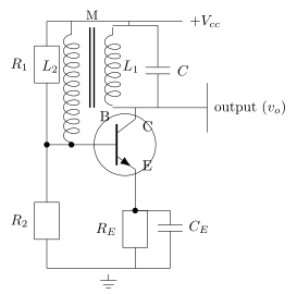
An oscillator converts DC power into a continuous, self-sustaining AC signal. In a transistor (tuned-collector) oscillator, energy fed back from an LC tank circuit in the collector to the base, in the correct phase, compensates for circuit losses each cycle, sustaining oscillation at the tank's resonant frequency.
What is an oscillator: An oscillator is an electronic circuit that generates a continuous, periodic (AC) output signal of a certain frequency without requiring any external AC input signal — it converts DC power (from the supply) into AC power at the output, using positive feedback.
- Labelled diagram of circuit (described): A common form is the tuned-collector (LC) oscillator. An NPN transistor is connected in CE (common-emitter) configuration. The collector is connected to the supply through a parallel LC tank circuit (, ) tuned to the desired oscillation frequency. A second coil (feedback/tickler coil), inductively coupled to , is connected between the base and emitter to feed a portion of the tank's oscillating voltage back to the base. Base-bias resistors () set the operating point; an emitter resistor (bypassed by ) provides stability. The output is taken across the tank circuit (collector) or via a separate coupling.
- Principle and working:
- On switching on, a small transient current pulse in the collector circuit sets the LC tank into damped oscillation at its natural (resonant) frequency . …
Unlock everything free for 14 days
- Full step-by-step solutions
- Concept-first explanations
- Methods, shortcuts & mistakes
- PYQ mapping + timed mock tests
Full access for 14 days. No credit card required.