Q.Draw the circuit diagram of half wave rectifier and explain its output waveform.
🔒You're viewing a preview — the full solution, concept, methods & PYQ mapping are locked.
🔒 Start your 14-day free trial to unlock the full solution →Concept understanding — P-N Junction Rectification
P-N Junction Rectification: Turning AC into DC
Imagine you have a water pipe with a one-way valve. Water can flow freely in one direction, but if you try to push it the other way, the valve slams shut and nothing moves. That's exactly what a p-n junction does — but with electric current instead of water.
The Intuition: Why Does It Let Current Flow Only One Way?
A p-n junction is made by joining two pieces of semiconductor: one p-type (with extra "holes" — think of them as positive charge carriers) and one n-type (with extra electrons). At the junction, something interesting happens.
Electrons from the n-side diffuse into the p-side, and holes from the p-side diffuse into the n-side. They meet and recombine, leaving behind a region with no free charge carriers — the depletion region. This region acts like a tiny battery, creating an internal electric field that points from n to p.
Now here's the key: this internal field opposes the flow of majority carriers. It's like a spring that's been compressed — it wants to push things back.
The depletion region is the reason a p-n junction conducts in only one direction. It's the "gatekeeper."
Forward Bias: Opening the Gate
Connect the p-side to the positive terminal of a battery and the n-side to the negative terminal. This is forward bias.
The external battery pushes holes from p toward n, and electrons from n toward p. They both march toward the depletion region. If the battery voltage is large enough (about 0.7 V for silicon), it overcomes the internal field. The depletion region shrinks, and current flows easily.
Think of forward bias as pushing the spring in the direction it wants to go — it compresses easily, and current flows.
Reverse Bias: Locking the Gate
Now swap the battery: p-side to negative, n-side to positive. This is reverse bias.
The battery pulls holes away from the junction on the p-side, and electrons away on the n-side. The depletion region widens — the spring stretches. No current flows (except a tiny leakage current from minority carriers, which we ignore for now).
If you apply too much reverse voltage, the junction breaks down and current surges. This is avalanche breakdown — it can destroy the diode unless it's designed for it (like a Zener diode).
The Precise Statement
Rectification: A p-n junction diode allows current to flow freely under forward bias and blocks current under reverse bias. This property converts alternating current (AC) into pulsating direct current (DC).
Mathematically, the current-voltage relationship is given by the Shockley diode equation:
I=IS(enVTV−1)
Where:
- I = diode current
- IS = reverse saturation current (tiny, typically 10−12 to 10−6 A)
- V = applied voltage (positive for forward bias, negative for reverse)
- n = ideality factor (usually 1 for ideal, 1–2 for real diodes)
- VT = thermal voltage ≈25.85 mV at room temperature (300 K)
For forward bias (V>0), the exponential term dominates, so I≈ISeV/(nVT) — current grows rapidly.
For reverse bias (V<0), eV/(nVT)≈0, so I≈−IS — a tiny constant leakage current.
How Rectification Works in Practice …
A single p-n junction diode conducts only when it is forward biased, so in a half-wave rectifier it lets through only the half of each ac cycle during which that condition holds, blocking the other half entirely. …
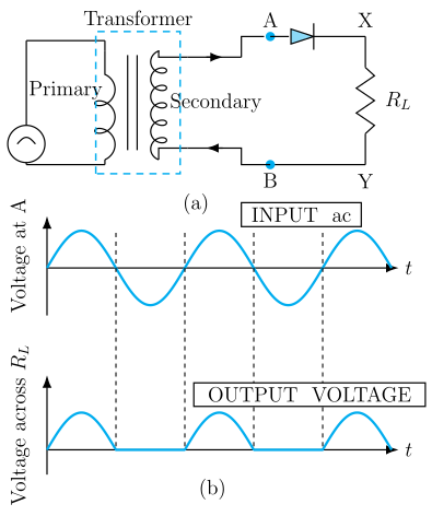
A single p-n junction diode conducts only when forward biased, so it passes only the positive half of each AC cycle, giving a pulsating (unidirectional but not steady) DC output.
Circuit: An AC source is connected in series with a single diode and a load resistor RL. The secondary of a step-down transformer feeds the diode, and the output is taken across RL.
Working: During the positive half-cycle of the input, the diode is forward biased and conducts, so current flows through RL and a voltage appears across it, following the shape of the input's positive half. During the negative half-cycle, the diode is reverse biased and does not conduct, so no current flows and the output is zero.
…
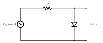
- CBSE 2026Set ANNUAL1 markMCQQ.A circuit consists of a diode biased with an emf source Vmsinωt through a resistor as shown in figure. The output obtained will be –(a) zero(b) like a half wave rectifier with positive cycle in output(c) like a half wave rectifier with negative cycle in output(d) like that of a full wave rectifier
›Reveal solutionSolution
With the output taken across the diode, it shows the (blocked) negative half-cycles, not the (conducted) positive ones.
In this circuit, the diode is oriented to conduct (forward biased) during the positive half-cycle of Vmsinωt. During the positive half-cycle, the diode conducts and behaves nearly like a short circuit, so almost all of the source voltage appears across the series resistor R, leaving a negligible voltage across the diode itself (output ≈0). During the negative half-cycle, the diode is reverse biased and does not conduct, so no current flows, there is no drop across R, and the entire (negative) source voltage appears across the diode. So the voltage across the diode (the output, …
- CBSE 2024Set A1 markMCQQ.P-N junction diode is used as (A) an amplifier (B) an oscillator (C) a modulator (D) a rectifier
›Reveal solutionSolution
A P-N junction diode is used as a rectifier → option (D).
A P-N junction diode conducts appreciable current only when it is forward biased and blocks current when reverse biased. This one-way conduction lets it convert alternating current (AC) into direct current (DC) — the process of **rectif …
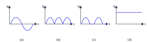
- CBSE 2023Set 55/1/11 markMCQQ.An ac source of voltage is connected in series with a p-n junction diode and a load resistor. The correct option for output voltage across the load resistance will be :(a)(b)(c)(d)
›Reveal solutionSolution
A single p-n junction diode in series with an ac source and load resistor acts as a half-wave rectifier: it conducts only during forward-bias (positive half-cycles), blocking the reverse half-cycles entirely. The output across the load is therefore a series of positive humps separated by zero-voltage gaps — option (c).
Figure — CBSE 2023 55/1/1 Q13
Why a p-n junction rectifies
A p-n junction diode is a one-way valve for current. When forward-biased (p-side positive relative to n-side), the barrier drops and current flows freely; when reverse-biased, the barrier widens and current is negligible. Connected in series with an ac source, the diode "chops off" half the waveform — the half that would reverse-bias it — leaving only the forward half-cycles to appear across the load. This is the essence of rectification: converting alternating current into a unidirectional (though still pulsating) current.
The circuit here has one diode, so it can only conduct during one polarity of the ac cycle. That makes it a half-wave rectifier.
Step-by-step reasoning
-
Identify the input
The ac source delivers a sinusoidal voltage V(t)=V0sin(ωt), which alternates between positive and negative half-cycles.
-
Diode behaviour during the positive half-cycle
When V(t)>0, the diode is forward-biased (assuming the diode's anode is connected to the positive terminal of the source). The diode conducts, and current flows through the load resistor RL. The output voltage across RL follows the input (minus a small diode drop ≈0.7V, often neglected in ideal analysis):
Vout≈V0sin(ωt)for 0<ωt<π.
- Diode behaviour during the negative half-cycle When V(t)<0, the diode is reverse-biased. It blocks current (ideally zero reverse current), so no current flows through RL. The output voltage is
Vout=0for π<ωt<2π.
-
The resulting waveform
Over one full period T=ω2π, the output consists of:
- A positive sinusoidal hump (the forward half-cycle),
- followed by a flat zero-voltage interval (the blocked reverse half-cycle).
This pattern repeats every cycle: positive hump, zero gap, positive hump, zero gap, … — the signature of half-wave rectification. …
-
- CBSE 2023Set F1 markMCQQ.Diode is used as (A) Amplifier (B) Oscillator (C) Modulator (D) Rectifier
›Reveal solutionSolution
A diode conducts only in forward bias, so it is used to rectify AC into DC.
A p-n junction diode offers very low resistance in forward bias and very high resistance in reverse bias — it allows current in essentially one direction only. This one-way property makes it ideal for rectification (half-wave or, with four diodes, full-wave bridge), converting alternating current into di …
- CBSE 2023Set B1 markMCQQ.Which device is used as a rectifier?(i) Junction diode(ii) Transformer(iii) Zener diode(iv) Photo diode
›Reveal solutionSolution
A p-n junction diode conducts current only when forward biased, which makes it the basic building block of a rectifier circuit.
A rectifier converts alternating current (AC), which reverses direction periodically, into direct current (DC), which flows in one direction only. A junction diode has the property of offering very low resistance when forward biased and very high resistance when reverse biased — it therefore allows current to pass during only one half of the AC cycle (half-wave rectifier) or, using two diodes with a centre-tapped …
- CBSE 2021Set ANNUAL1 markMCQQ.Diode can work as(a) rectifier(b) demodulator(c) modulator(d) amplifier.
›Reveal solutionSolution
A p-n junction diode's asymmetric (one-way) conduction makes it work as a rectifier, converting AC to pulsating DC.
A semiconductor diode has a very low resistance to current flow when forward biased (p-side positive) and a very high resistance when reverse biased (p-side negative). When an alternating voltage is applied across a diode in series with a load, the diode conducts current only during the half-cycle for which it is forward biased, and blocks current during the opposite half-cycle. The output current through the load is therefore unidirectional, though it varies in magnitude — this process of converting AC into a one-directional (pulsating DC) output is called rectification, and the diode used this way is a rectifier. Half-wave rectifiers use a single diode; full-wave rectifiers use two diodes (centre-tap) or four (bridge) to utilise both half-cycles.
…
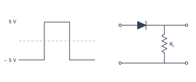
- CBSE 2019Set 55/5/11 markQ.Draw the output signal in a p-n junction diode when a square input signal of 10 V as shown in the figure is applied across it.
›Reveal solutionSolution
Figure — CBSE 2019 55/5/1 Q4 A p-n junction diode acts as a one-way switch: it conducts only when forward-biased (p-side positive). For a 10 V square wave input, the output is a half-wave rectified square wave — only the positive half of the input appears across the load; the negative half is blocked, giving zero output.
Why this works — the core idea
A p-n junction diode is not a linear resistor. Its behaviour depends entirely on the polarity of the applied voltage:
- Forward bias (p-side at higher potential than n-side): the depletion region narrows, majority carriers flow freely, and the diode acts like a closed switch — current passes, and voltage appears across the load.
- Reverse bias (n-side at higher potential): the depletion region widens, only a tiny leakage current flows (negligible here), and the diode acts like an open switch — no current, no voltage across the load.
This property is called rectification: converting an alternating (or bidirectional) signal into a unidirectional one. The simplest circuit using this is a half-wave rectifier — a single diode in series with a load resistor.
Watch outA common mistake is to think the diode conducts during both halves of the square wave. It does not. The diode is polarity-sensitive: only the half-cycle that makes the p-side positive relative to the n-side will turn it on. The other half leaves the output at zero.
Step-by-step solution
1. Identify the circuit configuration
The problem shows a p-n junction diode connected in series with a load resistor RL. The square wave input of amplitude 10 V is applied across the series combination. The output voltage Vo is taken across RL.
2. Understand the input signal
The input is a square wave that alternates between +10 V and −10 V with equal time periods. There is no zero-voltage interval — it jumps instantly from one extreme to the other.
3. Analyse the forward-bias half-cycle
When the input is +10 V, the p-side of the diode is at a higher potential than the n-side. This is forward bias. The diode turns on, and its voltage drop is small (≈0.7 V for silicon, but for an ideal diode we take it as zero). The entire input voltage appears across RL:
Vo=+10 V(during forward bias)
4. Analyse the reverse-bias half-cycle
When the input switches to −10 V, the p-side is now at a lower potential than the n-side. This is reverse bias. The diode turns off, behaving as an open circuit. No current flows through RL, so no voltage develops across it:
Vo=0 V(during reverse bias)
TipIn a half-wave rectifier, the output is not the negative half of the input inverted — it is simply zero. The diode does not "flip" the negative part; it blocks it entirely.
5. Describe the output waveform …
🎓Unlock everything free for 14 days
- ✓Full step-by-step solutions
- ✓Concept-first explanations
- ✓Methods, shortcuts & mistakes
- ✓PYQ mapping + timed mock tests
Full access for 14 days. No credit card required.