Q.Describe with circuit diagram an experiment to compare the e.m.f. of two cells with the help of a potentiometer.
You're viewing a preview — the full solution, concept, methods & PYQ mapping are locked.
Start your 14-day free trial to unlock the full solution →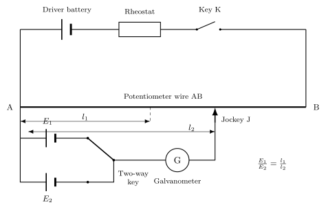
By balancing each cell in turn against the same potentiometer wire (fed by a steady driver current), the ratio of their EMFs equals the ratio of their balancing lengths, without drawing any current from either cell at balance.
CIRCUIT: A potentiometer wire AB of uniform cross-section is connected in series with a battery (the 'driver' battery), a rheostat, and a key K, so that a steady current I flows through the wire and sets up a uniform potential gradient along it. The two cells to be compared, E1 and E2, are connected (positive terminals both towards A) through a two-way key to a jockey and a galvanometer, so that either cell alone can be put in the secondary circuit at a time, in series with the galvanometer, between end A and a sliding jockey J on the wire.
PROCEDURE AND THEORY:
- First connect cell E1 into the secondary circuit (via the two-way key). Slide the jockey along AB until the galvanometer shows no deflection — this is the balance point, at distance l1 from A. At balance, no current is drawn from E1, so E1 equals the potential drop along AJ1: E1 = k * l1, where k is the potential gradient (potential drop per unit length) of the wire. …
Unlock everything free for 14 days
- Full step-by-step solutions
- Concept-first explanations
- Methods, shortcuts & mistakes
- PYQ mapping + timed mock tests
Full access for 14 days. No credit card required.