Physics · Ch 9 — Ray Optics and Optical Instruments
Refraction by a Lens
Refraction by a Lens
Refraction by a Lens: Image Formation
A lens forms an image by refracting light at two spherical surfaces. The process is broken into two steps:
- First surface (air to glass): The object forms an intermediate image .
- Second surface (glass to air): The image acts as a virtual object for the second surface, which then forms the final image .
This two-step approach uses the single-surface refraction formula (Eq. 9.15) for each interface.
Derivation of the Lens Maker's Formula
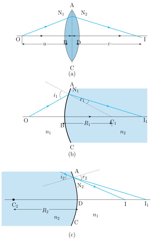
Step 1: Refraction at the first surface (ABC)
For the first interface, the object is at and the image is at . Applying the single-surface formula:
Here:
- = refractive index of the medium outside the lens (usually air, )
- = refractive index of the lens material
- = object distance from the first surface (negative by sign convention)
- = image distance from the first surface
- = radius of curvature of the first surface ()
Step 2: Refraction at the second surface (ADC)
For the second interface, the object is (virtual) and the final image is at . The medium on the right of ADC is and on the left is . Applying the formula:
Here:
- = distance of from the second surface (negative because measured against incident light direction)
- = final image distance from the second surface
- = radius of curvature of the second surface ()
Step 3: Adding the two equations
For a thin lens, the points and are very close to the optical centre, so . Adding the two equations gives:
Step 4: Defining the focal length
When the object is at infinity (), the image forms at the focus , so (focal length). Substituting:
Using the sign convention:
- (convex surface)
- (concave surface)
We get the lens maker's formula:
If the lens is in air (), this simplifies to:
Key points:
- This formula works for both convex and concave lenses.
- For a concave lens, is negative and is positive, making negative.
- It is used to design lenses of desired focal length by choosing appropriate radii.
The Thin Lens Formula
From the derivation, combining the general equation with the focal length definition gives:
Applying the sign convention:
- (object distance, negative)
- (image distance, positive for real images)
We obtain the thin lens formula:
Validity: This formula holds for:
- Both convex and concave lenses
- Both real and virtual images
Focal Points and Ray Tracing
A lens has two foci equidistant from the optical centre:
- First focal point (F): On the side of the original light source
- Second focal point (F'): On the opposite side
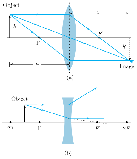
Three convenient rays for image construction:
- Parallel ray: A ray parallel to the principal axis, after refraction, passes through (convex) or appears to diverge from (concave). …
Drawn by us to help you understand the concept clearly, and verified to make sure it's accurate. For exams, practice from your textbook's own diagram.
Figure 9.16 is a three‑panel diagram that breaks down image formation by a thin double‑convex lens into two successive refractions at spherical surfaces.
Panel (a) shows the overall setup: a horizontal principal axis with the lens at the centre. The object is placed to the left of the lens, and the final real image is formed to the right. The lens is drawn as a symmetric double‑convex shape, with its two spherical surfaces meeting at the lens edges (points and ). The optical centre is not explicitly labelled but lies on the axis between the two surfaces.
Panel (b) isolates the first spherical surface (the left face of the lens). The object sends rays toward this surface. After refraction at , the rays converge to form an intermediate image inside the lens. The centre of curvature of this surface is , and its radius of curvature is . The refractive index outside the lens (to the left) is , and inside the lens (to the right of ) is .
Panel (c) shows the second spherical surface (the right face of the lens). The intermediate image now acts as a virtual object for this surface. Rays from refract at and emerge to form the final image on the right. The centre of curvature of this surface is , with radius . Note that the medium to the right of is again , while the lens interior (to the left of ) is .
The key physical idea is that a thin lens can be treated as two back‑to‑back spherical refracting surfaces. The image formed by the first surface becomes the object for the second. This step‑by‑step approach leads directly to the lens maker’s formula and the thin lens formula.
Applying the single‑surface refraction formula (Eq. 9.15) to each interface and adding the results (using the thin‑lens approximation ) gives:
Here:
- = object distance from the first surface (negative by sign convention)
- = image distance from the second surface (positive for a real image)
- (positive for convex surface facing the object)
- (negative for convex surface facing away from the object)
For an object at infinity (), the image distance becomes the focal length . Substituting the sign conventions yields the lens maker’s formula:
where is the refractive index of the lens material and that of the surrounding medium. For a lens in air, and , so: …
Drawn by us to help you understand the concept clearly, and verified to make sure it's accurate. For exams, practice from your textbook's own diagram.
Figure 9.17 is a ray diagram with two panels, (a) and (b), each showing how light rays from an object are refracted by a thin lens to form an image. The figure is designed to teach the three standard rays used for ray tracing, which are the same for both convex and concave lenses, but with different outcomes.
Panel (a): Convex lens (converging)
- The lens is represented by a double-arrow symbol at the centre, with its optical centre O on the principal axis.
- Two focal points are marked: F (first focus, on the side of the incoming light) and F′ (second focus, on the opposite side). They are equidistant from O.
- An object arrow (upright) is placed to the left of the lens, beyond F.
- Three rays are drawn from the tip of the object:
- A ray parallel to the principal axis — after refraction, it passes through F′.
- A ray through the optical centre O — it goes straight, undeviated.
- A ray through F (the first focus) — after refraction, it emerges parallel to the principal axis.
- These three refracted rays converge at a point on the right side of the lens, forming a real, inverted image (shown as an arrow pointing downward).
Panel (b): Concave lens (diverging)
- The lens symbol is again at the centre, with O, F, and F′ marked. For a concave lens, F is on the same side as the incoming light, and F′ on the opposite side.
- The same three rays are drawn from the object tip:
- A ray parallel to the principal axis — after refraction, it appears to diverge from F (the first focus). The actual refracted ray is drawn solid, and its backward extension (dashed line) goes through F.
- A ray through O — undeviated.
- A ray that appears to meet the second focus F′ before hitting the lens — after refraction, it emerges parallel to the principal axis. (Its backward extension is dashed.)
- The refracted rays diverge; their backward extensions (dashed lines) meet on the same side as the object, forming an erect, diminished virtual image (shown as an upright arrow, smaller than the object).
Physical idea taught:
The figure illustrates the three convenient rays for locating the image formed by a thin lens. For a convex lens, the rays converge to give a real image; for a concave lens, they diverge, and the virtual image is found by extending the rays backward. This method works for any object position and is the basis for deriving the lens formula.
Key formula developed with this figure:
The textbook uses the geometry of refraction at two spherical surfaces to derive the lens maker's formula and the thin lens formula. The central result is:
where:
- = object distance from the optical centre (negative by sign convention for real objects)
- = image distance from the optical centre (positive for real images, negative for virtual)
- = focal length of the lens (positive for convex, negative for concave) …