Q.A lamp is connected in series with a capacitor. Predict your observations for dc and ac connections. What happens in each case if the capacitance of the capacitor is reduced?
Concept understanding — Capacitive Reactance
Capacitive Reactance: The AC Resistance of a Capacitor
When you first meet a capacitor in a DC circuit, it behaves like a break in the wire once it's fully charged — no current flows. But in an AC circuit, something entirely different happens. The voltage keeps reversing, so the capacitor never finishes charging. It's constantly being filled, emptied, refilled, and re-emptied. This continuous back-and-forth means current does flow, but the capacitor resists that flow in a frequency-dependent way. That resistance is called capacitive reactance.
The Intuition: Why Frequency Matters
Imagine a water pipe with a flexible rubber membrane stretched across it (a crude capacitor). If you push water slowly from one side, the membrane bulges and eventually stops the flow — that's DC. But if you push and pull the water rapidly (AC), the membrane just vibrates, and water sloshes back and forth through the pipe. The faster you push-pull (higher frequency), the less the membrane impedes the flow. At very high frequencies, it's almost like the membrane isn't there.
In a capacitor, the "membrane" is the electric field between the plates. Higher frequency means the voltage changes faster, so the capacitor has less time to oppose the current. The result: capacitive reactance decreases as frequency increases.
The Precise Statement
Capacitive reactance XC is the opposition a capacitor offers to alternating current. It is measured in ohms (Ω), just like resistance. The formula is:
XC=2πfC1
Where:
- XC = capacitive reactance (ohms)
- f = frequency of the AC signal (hertz)
- C = capacitance (farads)
What the Formula Tells You
Three key relationships jump out:
- Inverse with frequency: Double the frequency, halve the reactance. At DC (f=0), XC becomes infinite — the capacitor blocks DC completely.
- Inverse with capacitance: A larger capacitor (more farads) offers less opposition. It can store more charge per volt, so it "gives way" more easily.
- No power dissipation: Unlike a resistor, a pure capacitor doesn't convert electrical energy to heat. Reactance is a reactive opposition — energy is stored and returned, not lost.
Do not confuse capacitive reactance with resistance. Resistance dissipates energy as heat; reactance stores and releases it. A capacitor in an AC circuit has zero real power loss (in the ideal case).
Phase: The Hidden Twist
There's a critical detail that separates reactance from resistance. In a purely resistive circuit, voltage and current peak at the same time — they are in phase. In a purely capacitive circuit, current leads voltage by 90∘ (or π/2 radians).
Why? Because current is the rate of change of charge: I=CdtdV. When the voltage is at its peak (not changing), the current is zero. When the voltage is crossing zero (changing fastest), the current is maximum. This quarter-cycle shift is baked into the definition of reactance.
The j (or i) in complex impedance accounts for this phase. The impedance of a capacitor is ZC=−jXC=jωC1, where ω=2πf. The negative sign indicates the 90∘ phase lead of current over voltage.
Worked Example
A 10 μF capacitor is connected to a 50 Hz mains supply. Find its reactance.
XC=2π×50×10×10−61=2π×5×10−41=3.1416×10⁻³¹≈318 Ω
At 500 Hz, the same capacitor gives XC≈31.8 Ω — ten times smaller for ten times the frequency.
Summary for Exams
- Capacitive reactance XC=2πfC1 (ohms)
- It decreases with increasing frequency and capacitance
- Current leads voltage by 90∘ in a pure capacitor
- No power is dissipated (ideal case)
- At DC (f=0), XC=∞ — the capacitor blocks steady current
Final answer: XC=2πfC1
Capacitive reactance, X_C = 1/(2πfC), and its inverse relationship with frequency is a key part of the NCERT Class 12 Physics chapter on alternating current, tested through numericals in CBSE boards and JEE Main. Anyone searching "capacitive reactance formula and phase difference class 12 physics" will find this current-leads-voltage explanation matches the standard NCERT derivation.
Why this formula?
Capacitive Reactance: Why XC=ωC1?
Let’s build the intuition from the ground up — starting with what a capacitor does in a circuit.
1. The Fundamental Behavior of a Capacitor
A capacitor stores charge. The defining equation is:
Q=CV
where:
- Q = charge on the plates (in coulombs)
- C = capacitance (in farads)
- V = voltage across the plates
But in an AC circuit, voltage changes continuously. So charge must also change — meaning current flows.
2. Relating Current to Voltage
Current is the rate of flow of charge:
I=dtdQ
Substitute Q=CV:
I=dtd(CV)
If C is constant (which it is for a fixed capacitor):
I=CdtdV
Key insight: The current through a capacitor is proportional to the rate of change of voltage, not the voltage itself.
3. Applying a Sinusoidal Voltage
In AC circuits, voltage is typically sinusoidal:
V(t)=V0sin(ωt)
where:
- V0 = peak voltage
- ω=2πf = angular frequency (rad/s)
Now find the current:
I(t)=Cdtd[V0sin(ωt)]=CV0⋅ωcos(ωt)
So:
I(t)=ωCV0cos(ωt)
4. The Phase Shift — Why It Matters
Notice:
- Voltage: sin(ωt)
- Current: cos(ωt)=sin(ωt+90∘)
Current leads voltage by 90∘ in a pure capacitor. This is the opposite of an inductor (where current lags).
5. Extracting the Reactance
Compare the amplitudes:
- Voltage amplitude: V0
- Current amplitude: I0=ωCV0
By Ohm’s law for AC (magnitude only):
Reactance=Current amplitudeVoltage amplitude=ωCV0V0=ωC1
Thus:
XC=ωC1=2πfC1
6. Why "Reactance" and Not "Resistance"?
- Resistance (R) dissipates energy as heat.
- Reactance (XC) stores and releases energy — no net power loss in an ideal capacitor.
The 1/ωC form tells you:
- High frequency (ω large) → XC small → capacitor acts like a short circuit.
- Low frequency (ω small) → XC large → capacitor acts like an open circuit (blocks DC).
7. The Complete AC Ohm's Law for Capacitors
In phasor form (including phase):
V~=I~⋅(−jXC)
where −j accounts for the 90∘ phase lag of voltage behind current.
Summary: The "Why" in One Line
Capacitive reactance XC=1/(ωC) arises because current is proportional to the rate of change of voltage (I=CdV/dt), and for a sinusoidal voltage, that rate of change scales with frequency ω.
Key exam point: Always remember the inverse relationship with frequency — this is the hallmark of capacitive behavior.
Concept: Capacitive Reactance — a capacitor blocks steady DC but offers frequency-dependent opposition (XC=2πfC1) to AC.
Reasoning:
- DC connection: For a steady DC source (f=0), the capacitor charges fully and then acts as an open circuit. No current flows after the initial transient, so the lamp does not glow.
- AC connection: For an AC source, the capacitor continuously charges and discharges. The reactance XC=2πfC1 limits the current. The lamp glows dimly if XC is large, or brightly if XC is small.
- Reducing capacitance C:
- In DC: still an open circuit after charging — lamp remains off.
- In AC: XC increases (since XC∝1/C), so current decreases — lamp becomes dimmer.
For DC, the lamp does not glow and reducing C has no effect; for AC, the lamp glows and reducing C makes it dimmer.
A capacitor blocks DC completely (lamp stays off) but allows AC to pass (lamp glows). Reducing capacitance increases the opposition to AC (higher capacitive reactance), making the lamp dimmer; for DC, reducing capacitance changes nothing — the lamp remains off.
The Core Idea: Capacitive Reactance
A capacitor does not behave the same way for direct current (DC) and alternating current (AC). The reason lies in how a capacitor stores and releases charge.
For DC, once the capacitor is fully charged, no further current flows in the circuit. The capacitor acts like an open switch — an infinite resistance to steady DC.
For AC, the voltage keeps reversing polarity. The capacitor continuously charges and discharges, so current flows back and forth through the circuit. The opposition to AC is not called resistance but capacitive reactance, given by:
XC=2πfC1
where f is the frequency of the AC supply and C is the capacitance. Notice: larger C means smaller XC (easier for current to flow), and smaller C means larger XC (harder for current to flow).
XC=2πfC1
Now let's apply this to the lamp-and-capacitor circuit.
Step-by-Step Analysis
1. DC Connection — What happens?
When you connect a DC source (like a battery) in series with the lamp and capacitor:
- Initially, a brief surge of current flows as the capacitor charges. The lamp may flash momentarily.
- Once the capacitor is fully charged (to the source voltage), current stops completely.
- The lamp goes out and stays out.
Why? For DC, after the transient, the capacitor behaves as an open circuit. No steady current can pass through a capacitor in a DC circuit.
A common mistake is to think a capacitor "blocks DC" instantly. In reality, there is a brief charging current — but for a steady DC source, the lamp will not glow continuously.
2. DC Connection — Effect of reducing capacitance
If you replace the capacitor with one of smaller capacitance:
- The charging time constant τ=RC becomes smaller (since C is smaller).
- The initial flash becomes even briefer.
- After charging, the lamp is still off — exactly as before.
Result: Reducing C does not change the final outcome. The lamp remains off for DC regardless of the capacitance value.
3. AC Connection — What happens?
When you connect an AC source (like mains supply) in series with the lamp and capacitor:
- The capacitor charges and discharges with each half-cycle of the AC.
- Alternating current flows continuously through the circuit.
- The lamp glows steadily.
Why? The capacitor offers a finite opposition XC to the AC. The current through the circuit is:
I=XCV=V⋅2πfC
where V is the RMS voltage of the AC source. Since current flows, the lamp lights up.
Think of the capacitor as a "frequency-dependent resistor" for AC — at 50 Hz (typical mains), it lets through enough current to light a lamp if C is chosen appropriately.
4. AC Connection — Effect of reducing capacitance
Now reduce the capacitance (say, from 10μF to 1μF):
- From XC=2πfC1, a smaller C gives a larger XC.
- The current I=V/XC becomes smaller.
- The lamp receives less power and glows more dimly.
If you keep reducing C enough, XC becomes so large that the current is negligible — the lamp may go out entirely.
Result: Reducing capacitance reduces the brightness of the lamp for AC.
Summary Table
| Connection | Initial behaviour | Effect of reducing C |
|---|---|---|
| DC | Lamp glows briefly, then goes off permanently | No change — lamp stays off |
| AC | Lamp glows steadily | Lamp becomes dimmer (higher XC, lower current) |
For DC, the lamp glows momentarily then goes off, and reducing capacitance does not change this; for AC, the lamp glows steadily, and reducing capacitance makes it dimmer.
Method: Qualitative Analysis of Capacitor Behaviour in DC and AC Circuits
This problem is solved using the concept of capacitive reactance and the steady-state behaviour of capacitors.
Step 1 – Understand the fundamental property of a capacitor
- A capacitor blocks steady DC after it is fully charged (acts as an open circuit).
- For AC, a capacitor offers frequency-dependent opposition called capacitive reactance:
XC=2πfC1
where f is frequency and C is capacitance.
Step 2 – Analyse the DC connection
- When DC is first switched on, a transient current flows as the capacitor charges.
- After charging (steady state), no current flows through the capacitor.
- Therefore, the lamp does not glow (or glows only momentarily and then goes off).
Step 3 – Analyse the AC connection
- For AC, the capacitor continuously charges and discharges, allowing alternating current to flow.
- The lamp glows continuously (though possibly dimmer than if connected directly, due to XC).
Step 4 – Effect of reducing capacitance
- For DC: Reducing C does not change the steady-state observation — the lamp still remains off (capacitor still blocks DC).
- For AC: From XC=2πfC1, reducing C increases XC. This reduces the current, so the lamp becomes dimmer.
Final Prediction Summary
| Connection | Observation | Effect of reducing C |
|---|---|---|
| DC | Lamp does not glow (steady state) | No change — lamp remains off |
| AC | Lamp glows | Lamp becomes dimmer |
Key concept: Capacitor blocks DC but allows AC, with opposition inversely proportional to capacitance.
Here are the common mistakes students make on this exact concept (Capacitive Reactance with DC and AC), along with how to avoid each.
Mistake 1: Thinking a capacitor blocks AC completely
The error:
Students often say: "A capacitor blocks DC and AC both."
They confuse the behavior of a capacitor with that of an inductor or a simple resistor.
Why it’s wrong:
A capacitor blocks DC (steady current) after it is fully charged, but allows AC to pass because it continuously charges and discharges. The opposition to AC is called capacitive reactance (XC), which is finite.
How to avoid:
Remember the charging/discharging cycle:
- For DC: Once charged, no further current flows → lamp does not glow (after initial flash).
- For AC: The capacitor alternately charges and discharges → current flows continuously → lamp glows.
Key formula:
XC=2πfC1
For DC, f=0 → XC→∞ (infinite opposition).
For AC, f>0 → XC is finite.
Mistake 2: Confusing the effect of reducing capacitance
The error:
Students say: "If capacitance is reduced, the lamp glows brighter in both DC and AC."
Why it’s wrong:
- DC: The lamp never glows (after initial transient) regardless of C — because XC is infinite for steady DC.
- AC: Reducing C increases XC (since XC∝1/C), so less current flows → lamp glows dimmer.
How to avoid:
Always apply the formula:
XC=2πfC1
- C↓ → XC↑ → current ↓ → lamp dimmer (AC).
- For DC, f=0 → XC is infinite regardless of C → lamp off.
Mistake 3: Forgetting the initial transient in DC
The error:
Students say: "For DC, the lamp never glows at all."
Why it’s wrong:
When DC is first switched on, the capacitor is uncharged → it acts like a short circuit momentarily → a brief surge of current flows → the lamp flashes once and then goes off.
How to avoid:
Think of the charging process:
- At t=0, VC=0, so the full battery voltage appears across the lamp → current flows.
- As the capacitor charges, current drops to zero → lamp goes off.
Exam tip: Mention the initial flash for DC — it shows deeper understanding.
Mistake 4: Mixing up series and parallel effects
The error:
Students treat the lamp and capacitor as if they are in parallel, or think the capacitor "stores" current for the lamp.
Why it’s wrong:
In series, the same current flows through both. The capacitor does not "supply" current — it opposes changes in voltage. The lamp’s brightness depends only on the current through the series circuit.
How to avoid:
Draw the circuit:
- Series: Current I is same everywhere.
- Lamp brightness ∝I2 (power).
- Capacitor’s reactance determines I via:
I=R2+XC2V
Quick Summary Table (Exam-Ready)
| Connection | Observation | Effect of reducing C |
|---|---|---|
| DC | Lamp flashes once, then off | No change (still off after flash) |
| AC | Lamp glows continuously | Lamp becomes dimmer |
Final tip: Always write the formula XC=1/(2πfC) in your answer — it’s the single most important tool to avoid mistakes.
- COMEDK 2026Set 2026-A1 markMCQQ.A source of alternating emf ε=ε0sin(ωt) is connected to a capacitor. Then the instantaneous current in the circuit is: ˋ (A) I=I0sin(ωt−2π) (B) I=2I0sin(ωt+2π) (C) I=I0sinωt (D) I=I0sin(ωt+2π)
›Reveal solutionSolution
For a purely capacitive AC circuit, current leads voltage by 90° (π/2 rad). Since the source emf is ε = ε₀ sin(ωt), the instantaneous current is I = I₀ sin(ωt + π/2), which corresponds to option (D).
Concept & Intuition
In a capacitor, the relationship between voltage and current is governed by I=CdtdV. When the voltage is sinusoidal, the derivative of sine is cosine, and cosine is just sine shifted forward by 90°. This means the current leads the voltage by a quarter-cycle. No resistance or inductance is present, so the phase shift is exactly ±90° — and because the current must lead, we add π/2 to the sine argument.
Step-by-step reasoning
-
Write the given emf
The source provides ε=ε0sin(ωt). This is the voltage across the capacitor (since it’s directly connected).
-
Recall the capacitor current–voltage relation
For a capacitor, I=CdtdV. Here V=ε0sin(ωt), so:
I=Cdtd[ε0sin(ωt)]=Cε0ωcos(ωt).
- Express cosine as a shifted sine Using the identity cos(ωt)=sin(ωt+π/2), we get:
I=Cε0ωsin(ωt+2π).
- Define the peak current Let I0=Cε0ω. Then:
I=I0sin(ωt+2π).
- Match with the options This matches option (D) exactly. Option (A) has a minus sign (current lagging), (B) has an extra √2 factor, and (C) has no phase shift — all incorrect for a pure capacitor.
Watch outA common mistake is to think current and voltage are in phase for a capacitor, as they are for a resistor. Remember: the derivative of sine is cosine, which gives a 90° lead — never a lag.
✓Final answerThe correct option is (D).
ANSWER: D
-
- COMEDK 2026Set 2026-A1 markMCQQ.An electronic device operates at 2 MHz . The oscillating circuit has an inductance 20×10−5H. What is the capacitive reactance of the resonant circuit? (A) 251.2Ω (B) 2512Ω (C) 1256Ω (D) 5024Ω
›Reveal solutionSolution
At resonance XC=XL=2πfL=2π(2×10⁶)(2×10⁻⁴)≈2512 Ω — option (B).
At resonance the capacitive reactance equals the inductive reactance:
XC=XL=2πfL
With f=2 MHz=2×10⁶ Hz and L=20×10−5 H=2×10⁻⁴ H:
XC=2π(2×10⁶)(2×10⁻⁴)=2π(400)≈2513 Ω≈2512 Ω
✓Final answerThe capacitive reactance is ≈2512 Ω — option (B).
- KCET 2025Set D-41 markMCQQ.A series LCR circuit containing an AC source of 100V has an inductor and a capacitor of reactances 24Ω and 16Ω respectively. If a resistance of 6Ω is connected in series, across the series combination of inductor and capacitor only is (A) 80V (B) 400V (C) 8V (D) 40V
›Reveal solutionSolution
Find the impedance, get the common series current, then take the voltage across L and C together — remembering they are 180∘ out of phase, so they subtract.
Given: V=100 V, XL=24 Ω, XC=16 Ω, R=6 Ω, all in series.
Step 1 — Net reactance.
In a series LCR circuit, VL leads the current by 90∘ and VC lags it by 90∘ — so they are 180∘ apart and act in opposition. The net reactance is their difference:
X=XL−XC=24−16=8 Ω
Step 2 — Impedance.
The resistive voltage is in phase with the current while the net reactive voltage is 90∘ out of phase, so they add as perpendicular vectors (Pythagoras in the impedance triangle):
Z=R2+(XL−XC)2=62+82=36+64=100=10 Ω
(A clean 6–8–10 triangle — a hint that we are on track.)
Step 3 — Current in the circuit.
Series circuit ⇒ the same current flows through R, L and C:
Irms=ZVrms=10100=10 A
Step 4 — Voltage across the series L–C combination.
The individual magnitudes are
VL=IXL=10×24=240 V,VC=IXC=10×16=160 V
But we must not add these arithmetically. Being in antiphase, the resultant across the L–C pair is their difference:
VLC=∣VL−VC∣=∣240−160∣=80 V
Equivalently, and more directly,
VLC=I∣XL−XC∣=10×8=80 V
Step 5 — Consistency check.
Across the resistor, VR=IR=10×6=60 V. Then the total supply voltage should come back out as
V=VR2+VLC2=602+802=3600+6400=10000=100 V ✓
which is exactly the source voltage given. The answer is consistent.
Option (B) (400 V) comes from adding VL+VC, the classic error.
✓Final answerThe correct option is (A) — 80V.
ANSWER: A
- COMEDK 2024Set 2024-A1 markMCQQ.An AC voltage source of variable angular frequency ω and fixed amplitude V0 is connected in series with a capacitance C and an electric bulb of resistance R (inductance zero). When ω is decreased (A) the bulb switches off (B) total impedance of the circuit is unchanged (C) the bulb glows brighter (D) the bulb glows dimmer
›Reveal solutionSolution
In a series RC circuit driven by a fixed‑amplitude AC source, decreasing the angular frequency increases the capacitive reactance, which raises the total impedance and reduces the current — so the bulb glows dimmer. The correct option is (D).
Concept & Intuition
The bulb’s brightness depends on the power it dissipates, which for a resistive bulb is proportional to the square of the RMS current through it. In a series RC circuit, the total impedance is
Z=R2+(ωC1)2.
As ω decreases, the capacitive reactance XC=1/(ωC) increases, making Z larger. Since the source voltage amplitude V0 is fixed, the current amplitude I0=V0/Z decreases. Less current means less power in the resistor — the bulb dims.
Step‑by‑step reasoning
- Identify the circuit and its impedance The source, capacitor, and resistor are in series. The impedance of a capacitor is purely reactive: ZC=1/(jωC), so its magnitude is XC=1/(ωC). The total impedance magnitude is
Z=R2+(ωC1)2.
- Relate current to impedance The source has fixed amplitude V0. The current amplitude is
I0=ZV0=R2+(ωC1)2V0.
As ω decreases, the term 1/(ωC) grows, so the denominator grows — hence I0 decreases.
- Connect current to bulb brightness The bulb is a pure resistor R. The average power dissipated is
P=21I02R=2[R2+(ωC1)2]V02R.
A smaller ω makes the denominator larger, so P becomes smaller. The bulb glows less brightly.
- Evaluate the options
- (A) “the bulb switches off” — No, it only dims; current never becomes exactly zero for finite ω.
- (B) “total impedance is unchanged” — False; impedance increases as ω decreases.
- (C) “the bulb glows brighter” — Opposite of what we found.
- (D) “the bulb glows dimmer” — Correct.
Watch outA common mistake is to think that decreasing frequency reduces the “opposition” of a capacitor. In fact, capacitive reactance is inversely proportional to frequency — lower frequency means higher reactance, not lower.
TipFor a quick check: at very low frequency (ω→0), the capacitor behaves like an open circuit, so current goes to zero and the bulb goes dark. At very high frequency, the capacitor acts like a short, so the bulb gets full current and glows at maximum brightness. Decreasing ω thus always moves toward dimmer.
✓Final answerThe correct option is (D).
ANSWER: D
- KCET 2022Set B-31 markMCQQ.A series resonant ac circuit contains a capacitance 10−6 F and an inductor of 10−4 H. The frequency of electrical oscillations will be (A) 2π105 Hz (B) 2π10 Hz (C) 105 Hz (D) 10 Hz
›Reveal solutionSolution
Resonance means XL=XC, which yields f0=1/(2πLC); plug in L=10−4H, C=10−6F.
1. Why the resonance condition takes this form
In a series LCR circuit the reactances are
XL=ωLandXC=ωC1
They act in opposition (the inductor voltage leads the current by 90∘, the capacitor voltage lags by 90∘), so the impedance is
Z=R2+(XL−XC)2
At resonance the two cancel, Z falls to its minimum R, and the current is maximum. Setting XL=XC:
ω0L=ω0C1⟹ω02=LC1⟹ω0=LC1
And since ω0=2πf0,
f0=2πLC1
2. Substitute the data
L=10−4 H,C=10−6 F
LC=10−4×10−6=10−10 s2
LC=10−10=10−5 s
3. Finish
f0=2π×10−51=2π105 Hz≈1.59×10⁴ Hz≈15.9 kHz
4. Watch the trap
Options (C) and (D) drop the 2π — they quote the angular frequency ω0=105 rad s−1 as though it were the frequency. The question asks for frequency of oscillations in Hz, so the 2π must stay. Option (B) corresponds to mis-taking LC as 10−1.
✓Final answerThe correct option is (A) — 2π105 Hz.
ANSWER: A
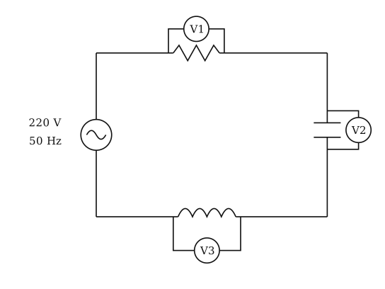
- COMEDK 2022Set 20221 markMCQQ.A series L-C-R circuit is connected to an AC source of 220 V and 50 Hz shown in figure. If the readings of the three voltmeters V1,V2 and V3 are 65 V, 415 V and 204 V respectively, the value of inductance and capacitance will be (A) 2.0 H, 5 μF (B) 1.0 H, 5 μF (C) 4.0 H, 6 μF (D) 1.0 H, 2 μF
›Reveal solutionSolution
Test option (A): L = 2.0 H, C = 5 μF → X_L = 628, X_C = 637, ratio ≈ 1.01 ✗ (needs ≈2.03). (C) and (D) fail similarly.
Concept: Series L-C-R — the voltmeter readings are V_R, V_C, V_L across each element (they all carry the same current I), and
V_source = √[V_R² + (V_L − V_C)²].
From the figure: V₁ = 65 V across R, V₂ = 415 V across C, V₃ = 204 V across L.
Consistency check with the source:
√[65² + (415 − 204)²] = √[4225 + 211²] = √[4225 + 44521] = √48746 ≈ 220.8 V ≈ 220 V ✓ — so the assignment of readings is right.
Use the reactance ratio. Since the same current I flows through all three,
X_C/X_L = V_C/V_L = 415/204 = 2.035.
ω = 2π(50) = 314 rad/s.
Test option (B): L = 1.0 H, C = 5 μF
X_L = ωL = 314 × 1.0 = 314 Ω
X_C = 1/(ωC) = 1/(314 × 5 × 10⁻⁶) = 1/(1.57 × 10⁻³) = 637 Ω
Ratio X_C/X_L = 637/314 = 2.03 ✓ — matches 415/204 = 2.035.
Self-consistency: I = V_L/X_L = 204/314 = 0.65 A. Then V_C = I X_C = 0.65 × 637 ≈ 414 V ✓ (given 415 V), and R = V_R/I = 65/0.65 = 100 Ω — all sensible.
Test option (A): L = 2.0 H, C = 5 μF → X_L = 628, X_C = 637, ratio ≈ 1.01 ✗ (needs ≈2.03). (C) and (D) fail similarly.
So L = 1.0 H, C = 5 μF.
✓Final answerThe correct option is (B) — 1.0 H, 5 μF
ANSWER: B
- COMEDK 2021Set 20211 markMCQQ.The formula of capacitative reactance is (A) 2πfC (B) 2πfC (C) 2πfC (D) 2πfC1
›Reveal solutionSolution
Dimensional sanity check: with f in Hz (1/s) and C in farads (C/V = As/V), 1/(fC) has units Vs/(A*s) = V/A = ohm, which is correct for a reactance. Note also that X_C falls as f increases (a capacitor blocks DC, f -> 0 gives X_C -> infinity), which only option (D) reproduces.
Concept: in an AC circuit the capacitive reactance is X_C = 1/(omega C), where omega = 2pif.
Hence X_C = 1/(2pif*C).
Dimensional sanity check: with f in Hz (1/s) and C in farads (C/V = As/V), 1/(fC) has units Vs/(A*s) = V/A = ohm, which is correct for a reactance. Note also that X_C falls as f increases (a capacitor blocks DC, f -> 0 gives X_C -> infinity), which only option (D) reproduces.
✓Final answerThe correct option is (D) — 2πfC1
ANSWER: D
- KCET 2019Set A-11 markMCQQ.For a transistor amplifier, the voltage gain (A) remains constant for all frequencies (B) is high at high and low frequencies and constant in the middle frequency range (C) is low at high and low frequencies and constant at mid frequencies (D) constant at high frequencies and low at low frequencies
›Reveal solutionSolution
The voltage gain of a transistor amplifier is low at both very high and very low frequencies, and remains constant only in the middle-frequency range — this is the classic band-pass shape of the gain-frequency curve.
The key idea here is that a transistor amplifier is not an ideal, frequency-independent device. Real amplifiers contain internal and external capacitances — like the coupling capacitors between stages, the bypass capacitor across the emitter resistor, and the transistor's own junction capacitances. These capacitors behave differently at different frequencies.
At low frequencies, the coupling and bypass capacitors have high reactance (XC=2πfC1), so they drop significant signal voltage and reduce the gain. At very high frequencies, the transistor's internal junction capacitances (like Cbe and Cbc) start to shunt the signal to ground, again reducing the gain. Only in the middle-frequency range — where these capacitors act as short circuits (for coupling/bypass caps) or open circuits (for junction caps) — does the gain stay flat and maximum.
This gives the amplifier a band-pass characteristic: gain rises from low to mid frequencies, stays constant over a mid-band, then falls off at high frequencies.
Now let's walk through the reasoning step by step.
-
Identify the frequency-dependent components.
A typical transistor amplifier (common-emitter, for example) has:
- Coupling capacitors (C1, C2) at input and output — these block DC but pass AC.
- A bypass capacitor (CE) across the emitter resistor — it shorts the emitter to ground for AC, preventing negative feedback at mid/high frequencies.
- Transistor internal capacitances (Cbe, Cbc) — these are always present and become important at high frequencies.
-
Low-frequency behaviour.
At low f, the reactance of C1, C2, and CE is large.
- C1 and C2 act as series impedances, dropping voltage and reducing signal transfer.
- CE no longer acts as a short; the emitter resistor now provides negative feedback, which reduces the gain. Result: voltage gain is low at low frequencies.
-
Mid-frequency behaviour.
At mid frequencies, the coupling and bypass capacitors have very low reactance — effectively short circuits. The transistor's junction capacitances still have high reactance — effectively open circuits. So all capacitors are "invisible" to the AC signal, and the amplifier operates at its designed, maximum gain.
Result: voltage gain is constant and maximum at mid frequencies.
-
High-frequency behaviour.
At high f, the coupling/bypass capacitors are already short circuits (no issue), but the transistor's internal junction capacitances now have low reactance. They shunt the signal from base to emitter or collector to base, reducing the effective input signal and the gain. The transistor's current gain (β) also falls off at high frequencies.
Result: voltage gain is low at high frequencies.
-
Combine the three regions.
The overall gain vs. frequency curve looks like this:
Frequency range Voltage gain Low Low (rising) Mid High and constant High Low (falling) This matches exactly with option (C).
Watch outA common mistake is to think that "high frequencies" means better performance — but in transistor amplifiers, the internal capacitances always limit the high-frequency response. Also, don't confuse this with an ideal op-amp, which has constant gain up to very high frequencies.
TipFor quick recall: the gain-frequency plot of a transistor amplifier looks like a plateau with slopes on both sides — like a table mountain. The flat top is the mid-band gain; the left slope is due to coupling/bypass capacitors; the right slope is due to transistor junction capacitances.
✓Final answerThe correct option is (C): voltage gain is low at high and low frequencies and constant at mid frequencies.
-
🎓Unlock everything free for 14 days
- ✓Full step-by-step solutions
- ✓Concept-first explanations
- ✓Methods, shortcuts & mistakes
- ✓PYQ mapping + timed mock tests
Full access for 14 days. No credit card required.