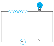
Q.A light bulb and an open coil inductor are connected to an ac source through a key as shown in Fig. 7.9.
🔒You're viewing a preview — the full solution, concept, methods & PYQ mapping are locked.
🔒 Start your 14-day free trial to unlock the full solution →Concept understanding — Inductive Reactance Change
Inductive Reactance Change – A First Look
Imagine you're pushing a child on a swing. If you push at just the right moment — when the swing is coming back toward you — each push adds energy and the swing goes higher. But if you push at random moments, sometimes you push against the swing's motion, and it barely moves. The swing "resists" being pushed at the wrong time.
An inductor in an AC circuit behaves exactly like that swing. It doesn't resist current the way a resistor does (by turning energy into heat). Instead, it resists changes in current — and the faster the current tries to change, the more the inductor pushes back.
The Core Intuition
An inductor is just a coil of wire. When current flows through it, it creates a magnetic field. If the current tries to change — say, increase or decrease — the magnetic field changes too. That changing field induces a voltage in the coil that opposes the change in current. This is Lenz's law in action: the induced voltage always fights the change that caused it.
So the inductor acts like a kind of "inertia" for current. The more rapidly the current tries to change, the stronger the opposition. In a DC circuit, once the current settles to a steady value, the inductor stops opposing — it becomes just a wire. But in an AC circuit, the current is always changing direction, so the inductor is always fighting.
The Precise Statement
Inductive reactance (XL) is the opposition an inductor offers to alternating current. It depends on two things:
- The inductance L of the coil (measured in henries, H) — bigger coil, more opposition.
- The frequency f of the AC supply (measured in hertz, Hz) — faster changes, more opposition.
The formula is:
XL=2πfL
Where:
- XL is in ohms (Ω)
- f is the frequency in Hz
- L is the inductance in H
Key point: Unlike resistance, which is constant for a given resistor, inductive reactance changes with frequency. Double the frequency, double the reactance. Halve the frequency, halve the reactance.
What "Inductive Reactance Change" Means
When we talk about "inductive reactance change," we mean: how XL varies when either the frequency or the inductance changes.
| Change | Effect on XL | Why? |
|---|---|---|
| Frequency increases | XL increases | Current changes faster → stronger opposition |
| Frequency decreases | XL decreases | Current changes slower → weaker opposition |
| Inductance increases | XL increases | More magnetic field → more opposition |
| Inductance decreases | XL decreases | Less magnetic field → less opposition |
A common mistake is to think inductive reactance behaves like resistance. It doesn't. Resistance dissipates energy as heat; reactance stores and releases energy in the magnetic field. Also, reactance depends on frequency — resistance usually doesn't.
A Simple Example …
Why this formula?
Inductive Reactance Change: Why the Formula Holds
Let's build this from first principles — understanding why inductive reactance behaves as it does, not just memorizing XL=2πfL.
1. The Core Idea: Opposition to Current Change
An inductor doesn't "resist" current like a resistor. Instead, it opposes changes in current due to self-induction.
- When current changes, the magnetic flux through the inductor changes.
- By Faraday's Law, a changing flux induces an emf (voltage) that opposes the change — this is Lenz's Law.
- The induced voltage is proportional to the rate of change of current:
vL=Ldtdi
Where:
- vL = induced voltage across inductor (V)
- L = inductance (henry, H)
- dtdi = rate of change of current (A/s)
2. Applying a Sinusoidal Current
In AC circuits, current is sinusoidal. Let:
i(t)=Imsin(ωt)
Where:
- Im = peak current (A)
- ω=2πf = angular frequency (rad/s)
- f = frequency (Hz)
Now compute the induced voltage:
vL=Ldtd[Imsin(ωt)]=L⋅Im⋅ωcos(ωt)
So:
vL=ωLImcos(ωt)
3. The Phase Shift: Voltage Leads Current
Notice:
- Current: sin(ωt)
- Voltage: cos(ωt)=sin(ωt+90∘)
Voltage leads current by 90∘ (or π/2 radians). This is a key property — the inductor causes a phase difference.
4. Defining Inductive Reactance
Reactance is the ratio of peak voltage to peak current (magnitude only, ignoring phase):
From above:
- Peak voltage: Vm=ωLIm
- Peak current: Im
Thus:
XL=ImVm=ωL
Since ω=2πf:
XL=2πfL
Where XL is in ohms (Ω).
5. Why It Changes with Frequency
The formula reveals the why:
- Higher frequency (f increases) → dtdi is larger for the same current amplitude → larger induced voltage → greater opposition → XL increases. …
The key idea is that inserting an iron rod increases the inductor's inductance L, which raises its inductive reactance XL=ωL.
- The bulb's brightness depends on the current through it. The current I=V/Z, where Z=R2+XL2 (the bulb's resistance R is fixed, and the coil's own resistance is negligible compared to its reactance).
- When the iron rod is inserted, the core's magnetic permeability μ increases sharply, so L increases. Since XL=2πfL, the reactance rises. …
Inserting an iron rod into the inductor increases its inductance, which raises the inductive reactance and reduces the current — so the bulb glows dimmer. The correct answer is (b) decreases.
Why this approach works — the concept first
The key idea here is that an inductor in an AC circuit opposes changes in current through a property called inductive reactance, XL. Unlike a resistor, which opposes current steadily, an inductor's opposition depends on how quickly the current is changing — and that's set by the AC frequency. But the inductor's design also matters: its inductance L depends on the core material.
When you slide an iron rod into the coil, you're changing the core from air (low permeability) to iron (high permeability). That dramatically increases L. And since XL=2πfL, the reactance jumps up. With a fixed AC voltage source, more reactance means less current — and the bulb, which glows based on the power it dissipates (P=I2R), gets dimmer.
A common mistake is to think the iron rod "conducts" current or somehow helps the bulb. It doesn't — the rod is insulated or just a solid piece; it only changes the magnetic properties of the coil. The bulb's brightness depends on current, not on magnetic field strength directly.
Step-by-step reasoning
1. Identify the circuit elements and their roles.
The bulb is a resistive load (its filament has resistance R). The open-coil inductor is a pure inductor (ideally, zero resistance) with inductance L. They're in series with an AC source of fixed voltage Vrms and fixed frequency f. The total impedance of the series combination is:
Z=R2+XL2,where XL=2πfL.
2. Understand what inserting the iron rod does.
The inductance of a coil depends on the magnetic permeability μ of the core material:
L=lμN2A,
where N is the number of turns, A is the cross-sectional area, and l is the length. Air has μ≈μ0 (permeability of free space). Iron has a relative permeability μr that can be hundreds or thousands — so μ=μrμ0 becomes huge. Therefore, L increases dramatically.
Lwith iron=μrLair(μr≫1)
3. Trace the effect on current.
The RMS current in the circuit is:
Irms=ZVrms=R2+(2πfL)2Vrms.
When L increases, XL increases, so Z increases. Since Vrms and f are fixed, Irms decreases.
4. Connect current to bulb brightness. …
Method: Predicting How a Circuit Responds When a Reactive Element Changes
This method applies whenever a question changes one physical property of an inductor or capacitor (inserting a core, changing frequency, adding a dielectric) and asks how the current or brightness of another element responds.
Steps
Step 1: Identify what stays fixed and what changes.
Write down the source voltage and frequency (usually fixed) separately from the component property being altered (here, the core material, which changes L). Never let the changing quantity be confused with the fixed ones.
Step 2: Express the total opposition to current (impedance) in terms of the changing quantity.
For a resistor in series with an inductor,
Z=R2+XL2,XL=2πfL
Identify which reactance formula governs the changing element (XL=ωL for an inductor, XC=1/(ωC) for a capacitor) and note whether the change increases or decreases that reactance.
Step 3: Track the chain of cause and effect through to the quantity being asked about. …
- COMEDK 2026Set 2026-M1 markMCQQ.A solenoid having resistance R=60Ω and inductance L=0.4H is connected to an AC source V=1002sin200t. Find the maximum current. (A) 1.732 A (B) 2.828 A (C) 1.414 A (D) 0.707 A
›Reveal solutionSolution
Impedance Z=R2+XL2=100Ω, so peak current Imax=Vmax/Z=2≈1.414 A.
The source is V=1002sin200t, so the peak voltage is Vmax=1002 V and the angular frequency is ω=200 rad/s.
Inductive reactance:
XL=ωL=200×0.4=80Ω
Impedance of the series R–L circuit: …
- COMEDK 2025Set 2025-A1 markMCQQ.What should be the value of the inductance of the coil which is to be connected to 220 V , 50 Hz supply so that maximum current of 32A flows through the circuit ? (A) L=(1522)H (B) L=(11π15)H (C) L=(15π11)H (D) L=(15222)H
›Reveal solutionSolution
The key idea is that for a purely inductive AC circuit, the maximum current is given by Imax=XLVmax, where XL=2πfL. Solving for L yields L=15π11 H, so the correct option is (C).
We are dealing with an AC circuit where only a coil (inductor) is connected to a 220 V, 50 Hz supply. The problem asks for the inductance such that the maximum current is 32 A. The key concept: in a purely inductive AC circuit, the voltage and current are related by inductive reactance, not resistance. The maximum (peak) values follow Ohm's law for reactance: Vmax=ImaxXL.
Let’s work through it step by step.
- Identify given quantities and convert to peak values The supply voltage is given as 220 V. In AC problems, unless stated otherwise, this is the RMS (root mean square) voltage. The relationship between RMS and peak (maximum) voltage is:
Vmax=VRMS×2
So:
Vmax=220×2 V
The maximum current is directly given:
Imax=32 A
- Recall the formula for inductive reactance For an inductor, the opposition to AC is called inductive reactance:
XL=2πfL
where f=50 Hz is the frequency and L is the inductance in henries.
- Apply Ohm’s law for peak values in an inductive circuit For a pure inductor, the peak voltage and peak current are related exactly like Ohm’s law:
Vmax=Imax×XL
Substitute the expressions:
2202=(32)×(2π×50×L)
- Simplify the equation Notice that 2 appears on both sides, so they cancel: 220=3×(2π×50×L) …
- COMEDK 2025Set 2025-E1 markMCQQ.In a pure inductive circuit, a sinusoidal voltage V(t)=200sin250t is applied to a pure inductance of L=0.02H. The current through the coil is: (A) 40sin[250t−2π] (B) 40cos[250t−2π] (C) 40sin[250t+2π] (D) 40cos[250t+2π]
›Reveal solutionSolution
In a pure inductive circuit, current lags voltage by 90° (π/2 rad). For V(t)=200 sin(250 t) and L=0.02 H, the current amplitude is 200/(250×0.02)=40 A, so the current is i(t)=40 sin(250 t − π/2). The correct option is (A).
Concept & Intuition
A pure inductor opposes changes in current. When a sinusoidal voltage is applied, the current cannot rise instantly with the voltage — it must “wait” for the voltage to build up. This delay is exactly one-quarter of a cycle, or a phase lag of 90° (π/2 radians). So for a voltage V(t)=V0sin(ωt), the current in a pure inductor is i(t)=I0sin(ωt−π/2). The amplitude I0 is given by Ohm’s law for AC: I0=V0/XL, where XL=ωL is the inductive reactance.
Step-by-step solution
-
Identify the given parameters
Voltage: V(t)=200sin(250t)
So amplitude V0=200 V, angular frequency ω=250 rad/s.
Inductance: L=0.02 H.
-
Compute the inductive reactance
XL=ωL=250×0.02=5 Ω
- Find the current amplitude
I0=XLV0=5200=40 A
- Apply the phase relationship In a pure inductor, current lags voltage by 90∘ (π/2 rad). Since voltage is a sine function, the current is:
-
- KCET 2024Set D-21 markMCQQ.An induced current of 2 A flows through a coil. The resistance of the coil is 10 Ω. What is the change in magnetic flux associated with the coil in 1 ms? (A) 0.2×10⁻² Wb (B) 2×10⁻² Wb (C) 22×10−2 Wb (D) 0.22×10⁻² Wb
›Reveal solutionSolution
The induced emf is found from Ohm’s law, then Faraday’s law gives the flux change. The answer is 2×10⁻² Wb, option (B).
The core idea here is Faraday’s law of electromagnetic induction: the induced emf in a coil equals the negative rate of change of magnetic flux through it. But we don’t have the emf directly — we have the current it drives through a known resistance. That’s where Ohm’s law steps in.
When a current flows because of an induced emf, the emf is simply E=IR. Once we know the emf, Faraday’s law tells us the magnitude of the flux change over a given time interval. The negative sign (Lenz’s law) tells us direction, but the question asks only for the magnitude of the change.
Let’s go step by step.
- Find the induced emf. The coil has resistance R=10 Ω and carries an induced current I=2 A. By Ohm’s law, the induced emf is
E=IR=2×10=20 V.
- Apply Faraday’s law. Faraday’s law states that the magnitude of the induced emf is
∣E∣=dtdΦ,
where Φ is the magnetic flux through the coil. For a small time interval Δt, if we assume the rate of change is constant,
∣E∣=Δt∣ΔΦ∣.
- Solve for the change in flux. Rearranging:
∣ΔΦ∣=∣E∣Δt.
Here Δt=1 ms=1×10⁻³ s. So
∣ΔΦ∣=20×10−3=2×10⁻² Wb. …
- COMEDK 2024Set 2024-E1 markMCQQ.When an A.C. source is connected to a inductive circuit, (A) voltage and current are in same phase. (B) voltage is ahead of current in phase. (C) the phase between voltage and current depends upon the value of inductance (D) voltage lags behind current in phase.
›Reveal solutionSolution
In a purely inductive AC circuit, the voltage leads the current by 90° (π/2 radians), so the correct choice is (B).
Concept and Intuition
When an AC source is connected to a purely inductive circuit (an ideal inductor with zero resistance), the relationship between voltage and current is not instantaneous — it’s governed by the inductor’s fundamental property: it opposes changes in current. This opposition is not a simple resistance; it’s a reactive effect that introduces a time shift, or phase difference, between voltage and current.
Think of it this way:
- For a resistor, voltage and current rise and fall together — they are in phase.
- For an inductor, the voltage depends on how fast the current is changing, not on the current itself.
- When the current is at its peak, it’s momentarily not changing (slope = 0), so the voltage is zero.
- When the current is crossing zero, it’s changing fastest, so the voltage is at its peak.
This swapping of peaks means the voltage reaches its maximum before the current does — hence voltage leads current by a quarter of a cycle (90°).
Step-by-Step Reasoning
- Recall the defining equation for an ideal inductor The voltage across an inductor is proportional to the rate of change of current through it:
v(t)=Ldtdi(t)
This is the key: voltage is not proportional to current itself, but to its derivative.
- Assume a sinusoidal current Let the current be:
i(t)=I0sin(ωt)
where I0 is the peak current and ω is the angular frequency.
- Compute the voltage Differentiate:
v(t)=Ldtd[I0sin(ωt)]=LI0ωcos(ωt)
Using the identity cos(ωt)=sin(ωt+90∘), we get:
v(t)=ωLI0sin(ωt+90∘)
So the voltage is a sine wave with the same frequency, but shifted ahead by 90∘ (or π/2 radians).
- Interpret the phase relationship
- Current: i(t)=I0sin(ωt)
- Voltage: v(t)=V0sin(ωt+90∘) The voltage reaches its positive peak a quarter-cycle before the current does. In AC circuit terminology, we say voltage leads current by 90° (or current lags voltage by 90°). …
- COMEDK 2024Set 2024-M1 markMCQQ.A coil of inductance 1H and resistance 100Ω is connected to an alternating current source of frequency π50 Hz. What will be the phase difference between the current and voltage? (A) 90∘ (B) 30∘ (C) 60∘ (D) 45∘
›Reveal solutionSolution
The phase difference in an LR circuit is given by ϕ=tan−1(RωL). With L=1H, R=100Ω, and f=50/πHz, we get ϕ=45∘, so the correct option is (D).
Concept & Intuition
In an AC circuit containing both resistance and inductance, the voltage and current are not in phase. The inductor causes the current to lag behind the voltage because it opposes changes in current. The resistor, however, keeps them in phase. The net phase difference depends on the ratio of inductive reactance (XL=ωL) to resistance (R). When XL=R, the phase angle is exactly 45∘ — a neat balance between the two effects.
Step-by-step solution
-
Find the angular frequency
The source frequency is f=π50Hz.
Angular frequency ω=2πf=2π⋅π50=100rad/s.
-
Compute the inductive reactance
XL=ωL=100×1=100Ω.
-
Identify the resistance
Given R=100Ω.
-
Phase difference formula for an LR circuit
For a series RL circuit, the phase angle ϕ by which current lags voltage is:
ϕ=tan−1(RXL) …
-
- COMEDK 2024Set 2024-M1 markMCQQ.A coil offers a resistance of 20 ohm for a direct current. If we send an alternating current through the same coil, the resistance offered by the coil to the alternating current will be : (A) 0Ω (B) Greater than 20Ω (C) Less than 20Ω (D) 20Ω
›Reveal solutionSolution
For DC, the coil’s resistance is just its ohmic resistance (20 Ω). For AC, the coil also exhibits inductive reactance, which adds to the total opposition (impedance), so the effective resistance to AC is greater than 20 Ω.
The key concept here is the difference between resistance and impedance.
A coil (inductor) has two properties:
- Resistance (R) — the same for DC and AC, due to the wire’s material.
- Inductance (L) — which only matters when the current changes, i.e., for AC.
For DC, the current is steady, so the inductor behaves like a plain resistor: opposition = R=20 Ω.
For AC, the changing current induces a back emf that opposes the flow. This effect is called inductive reactance (XL=2πfL). The total opposition to AC is the impedance Z=R2+XL2, which is always greater than R alone (unless XL=0, which only happens at DC).
Thus, the coil offers more opposition to AC than to DC.
-
Identify the DC case
For direct current, frequency f=0, so inductive reactance XL=2πfL=0.
The only opposition is the ohmic resistance: R=20 Ω.
-
Identify the AC case
For alternating current, f>0, so XL>0.
The total opposition (impedance) is:
Z=R2+XL2
Since XL>0, we have Z>R.
- Compare …
- COMEDK 2023Set 2023-E1 markMCQQ.What should be the inductance of an inductor connected to 200 V,50 Hz source so that the maximum current of 2 A flows through it? (A) π2H (B) 2πH (C) π2H (D) 2πH
›Reveal solutionSolution
Peak current 2 A gives rms current 1 A, so XL=200Ω and L=XL/(2πf)=2/π H.
Maximum (peak) current I0=2 A, so rms current Irms=I0/2=1 A.
Inductive reactance:
XL=IrmsVrms=1200=200Ω.
Since XL=2πfL: …
- COMEDK 2023Set 2023-M1 markMCQQ.In the case of an inductor (A) voltage lags the current by π/2 (B) voltage leads the current by π/2 (C) voltage leads the current by π/3 (D) voltage leads the current by π/4
›Reveal solutionSolution
For an ideal inductor v=Ldi/dt, so the voltage is 90∘ ahead of the current — the voltage leads the current by π/2.
For a pure inductor, if i=I0sinωt then
v=Ldtdi=ωLI0cosωt=ωLI0sin(ωt+2π). …
- COMEDK 2021Set 20211 markMCQQ.What should be the value of self-inductance of an inductor that should be connected to 220 V 50 Hz supply, so that a maximum current of 0.9 A flows through it? (A) 11 H (B) 2 H (C) 1.1 H (D) 5 H
›Reveal solutionSolution
[!TLDR]
Use I0=V0/(2πfL) with peak voltage V0=2202 and peak current 0.9 A to get L≈1.1 H.
Concept
In a purely inductive AC circuit (CBSE Class-12 Alternating Current), the inductor limits current through its inductive reactance XL=ωL=2πfL. The maximum (peak) current relates to the peak voltage by I0=V0/XL.
Solution
Given Vrms=220 V, f=50 Hz, maximum (peak) current I0=0.9 A.
Peak voltage:
V0=2Vrms=1.414×220=311.1 V.
Inductive reactance needed:
XL=I0V0=0.9311.1=345.7 Ω.
Since XL=2πfL, …
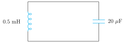
- KCET 2020Set A-11 markMCQQ.In the given circuit, the resonant frequency is
 (A) 15.92 Hz
(B) 159.2 Hz
(C) 1592 Hz
(D) 15910 Hz
(A) 15.92 Hz
(B) 159.2 Hz
(C) 1592 Hz
(D) 15910 Hz›Reveal solutionSolution
Read L and C off the circuit, convert to SI, and apply fr=2πLC1.
Step 1 — Read the circuit.
The figure shows a series LC circuit with:
- Inductor: L=0.5 mH
- Capacitor: C=20 μF
Step 2 — The concept behind resonance.
At resonance the inductive and capacitive reactances cancel exactly:
XL=XC⟹ωL=ωC1⟹ω2=LC1⟹ωr=LC1.
Since ω=2πf,
fr=2πLC1
Step 3 — Convert to SI units (where most errors happen).
L=0.5 mH=0.5×10⁻³ H=5×10⁻⁴ H
C=20 μF=20×10−6 F=2×10⁻⁵ F
Step 4 — Compute LC.
LC=(5×10⁻⁴)(2×10⁻⁵)=10×10−9=1×10⁻⁸ s2
LC=10−8=10−4 s
(The numbers are chosen so this comes out exact — a good sign we've converted correctly.)
Step 5 — Compute fr. …
🎓Unlock everything free for 14 days
- ✓Full step-by-step solutions
- ✓Concept-first explanations
- ✓Methods, shortcuts & mistakes
- ✓PYQ mapping + timed mock tests
Full access for 14 days. No credit card required.