Q.How does the sign of the phase angle ϕ, by which the supply voltage leads the current in an LCR series circuit, change as the supply frequency is gradually increased from very low to very high values?
🔒You're viewing a preview — the full solution, concept, methods & PYQ mapping are locked.
🔒 Start your 14-day free trial to unlock the full solution →Concept understanding — Resonance in AC Circuits
Resonance in AC Circuits
A series circuit containing a resistor R, an inductor L and a capacitor C driven by an AC source exhibits resonance — a sharp condition at which the circuit responds most strongly.
The Competing Reactances
In a series RLC circuit the inductor and capacitor oppose the current in opposite senses. Their reactances are
XL=ωL,XC=ωC1
where ω=2πf is the angular frequency. As frequency rises, XL grows while XC shrinks. The total impedance is
Z=R2+(XL−XC)2
The Resonance Condition
At one special frequency the two reactances become exactly equal and cancel:
XL=XC⇒ω0L=ω0C1⇒ω0=LC1
The corresponding resonant frequency is
f0=2πLC1
At this frequency the impedance falls to its minimum, Z=R (purely resistive), so the current reaches its maximum value
Imax=RVrms
Because the reactances cancel, the source voltage and current are exactly in phase — the power factor is 1 at resonance.
Physical Picture
At resonance energy sloshes back and forth entirely between the inductor's magnetic field and the capacitor's electric field, cycle after cycle. The source only has to make up the small amount of energy lost as heat in R. This is the electrical analogue of a swing pushed at its natural frequency: a small periodic drive builds a large oscillation.
Sharpness and the Q-factor
How sharply the current peaks around f0 is measured by the quality factor:
Q=Rω0L=R1CL
A large Q (small R) gives a tall, narrow resonance curve — the circuit is highly selective, responding to a very narrow band of frequencies. A small Q gives a broad, flat peak.
Why It Matters …
Why this formula?
Resonance in AC Circuits: Why the Key Formulas Hold
Resonance in an AC circuit occurs when the inductive reactance (XL) and capacitive reactance (XC) exactly cancel each other out. Let's build the understanding step-by-step.
1. The Core Condition for Resonance
Consider a series RLC circuit (resistor R, inductor L, capacitor C) driven by an AC voltage source V=V0sin(ωt).
The total impedance Z of the series combination is:
Z=R+j(XL−XC)
where:
- XL=ωL (inductive reactance)
- XC=ωC1 (capacitive reactance)
- j=−1
Why resonance happens:
The circuit "wants" to let maximum current flow. The opposition to current comes from both resistance and reactance. But reactance can be negative (capacitive) or positive (inductive). When they are equal in magnitude but opposite in sign, they cancel:
XL=XC
This is the fundamental condition — not a formula to memorize, but a logical consequence of impedance minimization.
2. Deriving the Resonant Frequency
From XL=XC:
ωL=ωC1
Multiply both sides by ω:
ω2LC=1
Thus:
ω0=LC1
Since ω=2πf, the resonant frequency in hertz is:
f0=2πLC1
Why this makes sense:
- A larger L or C means the circuit takes longer to "oscillate" — lower frequency.
- A smaller L or C means faster oscillations — higher frequency.
- The product LC controls the natural time scale of the circuit.
3. What Happens at Resonance — Key Consequences
(a) Impedance is Minimum (Purely Resistive)
At resonance, XL−XC=0, so:
Z=R+j(0)=R
Why: The reactive parts cancel, leaving only the resistance. The circuit behaves like a pure resistor.
(b) Current is Maximum
From Ohm's law for AC:
I=ZV
At resonance, Z=R (minimum possible), so current is maximum:
Imax=RV
Why: The opposition to current is smallest when reactance cancels.
(c) Voltage Across L and C Can Be Very Large
The voltage across the inductor:
VL=I⋅XL=RV⋅ω0L
The voltage across the capacitor:
VC=I⋅XC=RV⋅ω0C1
Since XL=XC at resonance, VL=VC in magnitude, but they are 180° out of phase — they cancel each other in the loop.
Why this is important:
If R is small, VL and VC can be many times larger than the source voltage V. This is called voltage magnification — a key concept for tuned circuits and filters.
--- …
Concept: Resonance in AC Circuits — the phase angle ϕ depends on whether the inductive reactance XL=ωL or capacitive reactance XC=1/(ωC) dominates.
Reasoning:
- For an LCR series circuit, tanϕ=RXL−XC=RωL−1/(ωC).
- At very low frequencies, XC≫XL, so XL−XC<0 → ϕ is negative (current leads voltage).
- At resonance (ω=ω0=1/LC), XL=XC → ϕ=0. …
The phase angle ϕ in a series LCR circuit shifts from −2π (current leads voltage) at very low frequencies, through zero at resonance, to +2π (voltage leads current) at very high frequencies — a continuous change of 180∘.
The behaviour of an LCR series circuit is governed by one central idea: resonance. At any frequency, the total opposition to current is the impedance Z, which combines resistance R, inductive reactance XL=ωL, and capacitive reactance XC=ωC1. The phase angle ϕ tells us whether the circuit looks more like a capacitor (current leads) or an inductor (current lags).
The formula for ϕ is:
tanϕ=RXL−XC=RωL−ωC1
The sign of ϕ depends entirely on whether XL>XC (positive ϕ, voltage leads) or XL<XC (negative ϕ, current leads). At resonance, XL=XC, so ϕ=0.
Now let's track what happens as frequency sweeps from very low to very high.
-
At very low frequencies (ω→0)
- XL=ωL→0 (inductor acts like a short)
- XC=ωC1→∞ (capacitor blocks current)
- So XL−XC≈−∞, making tanϕ→−∞
- This means ϕ→−2π (or −90∘)
- Current leads voltage — the circuit is predominantly capacitive.
-
As frequency increases (but still below resonance)
- XL grows linearly, XC falls hyperbolically
- The difference XL−XC becomes less negative
- ϕ rises from −2π toward zero
- The circuit becomes less capacitive, more resistive.
-
At resonance (ω=ω0=LC1)
- XL=XC, so tanϕ=0
- ϕ=0 — voltage and current are in phase
- The circuit behaves as a pure resistor; impedance is minimum (Z=R).
-
Above resonance (ω>ω0)
- XL now exceeds XC
- XL−XC becomes positive, so tanϕ>0
- ϕ becomes positive and increases toward +2π
- Voltage leads current — the circuit is predominantly inductive.
-
At very high frequencies (ω→∞)
- XL→∞ (inductor blocks), XC→0 (capacitor shorts)
- XL−XC→+∞, so tanϕ→+∞
- ϕ→+2π (or +90∘)
- Voltage leads current by a quarter cycle. …
Method: Tracking How the Phase Angle Changes Across a Range of Frequencies in a Series LCR Circuit
This method applies to any question asking how a series LCR circuit's phase angle, impedance character, or "which element dominates" changes as frequency is swept from very low to very high.
Steps
Step 1: Write the general phase-angle formula
tanϕ=RXL−XC=RωL−ωC1
This single formula governs the phase angle at every frequency — track the SIGN of the numerator as ω changes.
Step 2: Evaluate the two reactances at the extremes
As ω→0: XL=ωL→0 (inductor looks like a short) while XC=1/(ωC)→∞ (capacitor blocks). As ω→∞: the opposite happens — XL→∞, XC→0. This tells you the circuit is capacitive-dominated at low frequency and inductive-dominated at high frequency.
Step 3: Identify the crossover point — resonance …
- KCET 2025Set D-41 markMCQQ.In domestic electric mains supply, the voltage and the current are (A) AC voltage and DC current (B) DC voltage and DC current (C) DC voltage and AC current (D) AC voltage and AC current
›Reveal solutionSolution
The mains is an alternating voltage source, and an alternating voltage across a circuit necessarily drives an alternating current — so both quantities are AC.
Step 1 — What the mains actually delivers.
Electricity is generated by AC generators (alternators) and distributed to homes as an alternating voltage. In India it is
V=V0sin(ωt),Vrms=230 V,f=50 Hz
so the peak value is V0=2×230≈325 V, and the polarity reverses 2f=100 times each second.
Step 2 — Why the current must also be AC.
The current in any element of the household circuit is determined by that applied voltage and the element's impedance Z:
I=ZV=ZV0sin(ωt−ϕ)
Because V oscillates sinusoidally and reverses sign every half-cycle, so does I. There is no passive element that can convert an alternating driving voltage into a steady one-directional current — that requires an active rectifier (a diode circuit), which is exactly what appliances that need DC (chargers, LED drivers, TVs) contain inside themselves. The mains supply itself, before rectification, is AC through and through.
Step 3 — Why AC is used at all. …
- COMEDK 2025Set 2025-A1 markMCQQ.In which of the following circuit do we find the current and voltage in phase? (A) A purely resistive circuit (B) A circuit in which an inductor and a capacitor are in series. (C) A purely Inductive circuit (D) A purely capacitive circuit
›Reveal solutionSolution
In an AC circuit, current and voltage are in phase only when the net reactance is zero — that is, when the circuit is purely resistive. The correct option is (A).
Concept & Intuition
In alternating current (AC) circuits, the phase relationship between voltage and current depends on the circuit’s impedance.
- A resistor has no phase shift: voltage and current rise and fall together.
- An inductor causes current to lag voltage by 90°.
- A capacitor causes current to lead voltage by 90°. When these reactive elements are combined, the net phase shift is determined by the difference between inductive and capacitive reactance. Only when the total reactance is zero (purely resistive) do voltage and current align perfectly in phase.
Step-by-step reasoning
-
Purely resistive circuit (Option A)
- Impedance is just Z=R (real, no imaginary part).
- Ohm’s law: V=IR holds instantaneously.
- Therefore, V and I are exactly in phase.
- ✓ This is the condition we are looking for.
-
Series LC circuit (Option B)
- Impedance Z=j(ωL−ωC1), purely imaginary.
- At resonance, ωL=ωC1, so Z=0 (theoretically a short circuit).
- Even at resonance, the voltage and current are not in phase — the circuit behaves as a pure resistance only if there is also a resistor. Without resistance, the phase is either +90° or –90° (or undefined at resonance).
- ✗ Not in phase.
-
Purely inductive circuit (Option C)
- Impedance Z=jωL, purely imaginary positive.
- Current lags voltage by exactly 90∘.
- ✗ Not in phase.
-
Purely capacitive circuit (Option D) …
- COMEDK 2025Set 2025-E1 markMCQQ.A series LCR circuit having R=44Ω, L=2H and C=25μ F is connected to a variable frequency of 220 V . What is the average power transferred to the circuit in one complete cycle if the frequency of supply equals the natural frequency of the circuit? (A) 2.1 kW (B) 4.2 kW (C) 1.1 kW (D) 1.2 kW
›Reveal solutionSolution
At resonance, the impedance is purely resistive and minimum, so the average power is simply V2/R. For this circuit, P=(220)2/44=1100 W=1.1 kW, which corresponds to option (C).
Concept and intuition:
In an LCR series circuit, the average power transferred over a complete cycle depends on the phase angle between voltage and current. At the natural (resonant) frequency, the inductive and capacitive reactances cancel each other (XL=XC), so the impedance is purely resistive and minimum (Z=R). The power factor becomes 1, meaning all the power supplied by the source is dissipated in the resistor. Therefore, the average power is simply the DC power formula P=Vrms2/R.
Step-by-step solution:
-
Identify the condition: The problem states the supply frequency equals the natural (resonant) frequency of the circuit. At resonance, XL=XC, so the total impedance Z=R2+(XL−XC)2=R.
-
Recall the average power formula: For an AC circuit, the average power over one cycle is
Pavg=VrmsIrmscosϕ
where cosϕ is the power factor. At resonance, ϕ=0, so cosϕ=1.
- Find the rms current: Since Z=R, the rms current is
Irms=ZVrms=RVrms.
- Substitute into power formula: Pavg=Vrms⋅RVrms⋅1=RVrms2. …
-
- COMEDK 2025Set 2025-M1 markMCQQ.An LCR series ac circuit is at resonance with 10 V each across L,C and R . If the resistance is halved, the respective voltage across R,C and L are (A) 5 V,10 V,10 V (B) 10 V,5 V,5 V (C) 5 V,5 V,5 V (D) 10 V,20 V,20 V
›Reveal solutionSolution
At resonance the supply voltage appears across R, so VS=10V. Halving R doubles the current, leaving VR=10V unchanged while VC and VL double to 20V each — order R,C,L=10V,20V,20V, option (D).
Concept. In a series LCR circuit at resonance, XL=XC, so the reactive voltages across L and C cancel and the impedance is purely resistive, Z=R. The whole supply voltage then drops across R.
Step 1 — Initial conditions.
Given VR=VL=VC=10V at resonance. Since Z=R, the supply voltage is
VS=VR=10 V,I0=RVS=R10.
The reactances (fixed L and C) satisfy I0XL=I0XC=10V.
Step 2 — Halve the resistance.
The source voltage is unchanged, so with R′=R/2 the new current is
I′=R′VS=R/2VS=2RVS=2I0.
Step 3 — New voltage across R. …
- COMEDK 2024Set 2024-E1 markMCQQ.In the A.C. circuit given below, voltmeters V1 and V2 read 100 V each. Find the reading of the voltmeter V3 and the ammeter A. (A) 220 V, 2 A (B) 110 V, 2 A (C) 110 V, 4 A (D) 220 V, 1 A
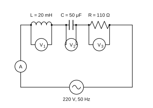
›Reveal solutionSolution
Since VL=VC, they cancel and V3=Vsupply=220 V; I=220/110=2 A.
For a series LCR circuit the supply voltage relates to the element voltages by
V=VR2+(VL−VC)2
Given V1=VL=100 V and V2=VC=100 V, so VL−VC=0.
Hence VR=V3=V2−0=V=220 V. …
- COMEDK 2023Set 2023-M1 markMCQQ.In the series L-C-R circuit shown, the impedance is (A) 200Ω (B) 100Ω (C) 300Ω (D) 500Ω
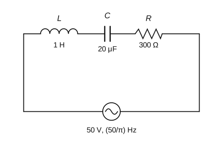
›Reveal solutionSolution
With ω=100 rad/s, XL=100Ω and XC=500Ω, so Z=R2+(XL−XC)2=3002+4002=500Ω.
Angular frequency:
ω=2πf=2π⋅π50=100 rad/s.
Reactances:
XL=ωL=100×1=100Ω,
XC=ωC1=100×20×10−61=2×10−31=500Ω. …
- COMEDK 2023Set 2023-M1 markMCQQ.In an electrical circuit R,L,C and AC voltage source are all connected in series. When L is removed from the circuit, the phase difference between the voltage and the current in the circuit is π/3. If instead C is removed from the circuit, the phase difference is again π/3. The power factor of the circuit is (A) 1/2 (B) 12 (C) 1 (D) 23
›Reveal solutionSolution
Equal phase angles in both cases mean XL=XC, so the RLC circuit is at resonance with power factor =1.
With L removed, the R–C circuit has tanϕ=RXC=tan3π, so XC=3R.
With C removed, the R–L circuit has tanϕ=RXL=tan3π, so XL=3R. …
- COMEDK 2021Set 20211 markMCQQ.For the same resonant frequency, if L is changed from L to 3L, then capacitance should change from C to (A) 3C (B) 3C (C) 32C (D) 2C
›Reveal solutionSolution
So the capacitance must be increased to 3C.
Concept: series LCR resonance occurs at f = 1/(2pisqrt(LC)), so at a fixed resonant frequency the product LC must stay constant.
L1 C1 = L2 C2
L * C = (L/3) * C2
=> C2 = 3C. …
- COMEDK 2021Set 2021-B1 markMCQQ.A series LCR circuit with inductance 0.12 H, Capacitance 480nF and resistance 23 ohms is connected to a 230 V variable frequency supply, the maximum power absorbed by the circuit is (A) 460 W (B) 4600 W (C) 2300 W (D) 230 W
›Reveal solutionSolution
At resonance the reactances cancel and power is maximum: Pmax=Vrms2/R=2302/23=2300 W.
In a series LCR circuit, power is maximum at the resonant frequency, where XL=XC and the impedance equals R. Then
Pmax=RVrms2=23(230)2=2352900=2300 W. …
- KCET 2019Set A-11 markMCQQ.An antenna uses electromagnetic waves of frequency 5 MHz. For proper working, the size of the antenna should be (A) 15 m (B) 300 m (C) 15 km (D) 3 km
›Reveal solutionSolution
For efficient radiation, the antenna length must be comparable to the wavelength of the signal. For a 5 MHz wave, the wavelength is 60 m, so a practical antenna size is about 15 m (quarter-wavelength). The correct option is (A).
The key idea here is that an antenna works efficiently only when its physical size is of the same order as the wavelength of the electromagnetic wave it is meant to transmit or receive. This is not an arbitrary rule — it comes from the physics of how oscillating charges radiate energy. If the antenna is too small compared to the wavelength, the radiated power is negligible; if it is much larger, it becomes impractical and directional.
For a simple dipole or monopole antenna, the most common design is a quarter-wavelength (λ/4) antenna. This length gives a good impedance match and efficient radiation. The problem asks for the "proper working" size, which in standard exam context means the minimum practical size for efficient radiation — and that is λ/4.
Let’s work it out.
- Find the wavelength of the electromagnetic wave. The relationship between frequency f and wavelength λ for any EM wave in vacuum (or air) is:
λ=fc
where c=3×10⁸ m/s is the speed of light.
- Plug in the given frequency f=5 MHz =5×10⁶ Hz:
λ=5×1063×108=60 m
- Determine the antenna size for proper working. The standard rule: the antenna length L should be at least λ/4 for efficient radiation. So: L=4λ=460=15 m …
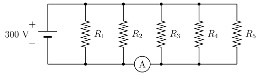
- KCET 2018Set A-11 markMCQQ.Five identical resistors each of resistance R=1500 Ω are connected to a 300 V battery as shown in the circuit. The reading of the ideal ammeter A is
 (A) 51 A
(B) 53 A
(C) 52 A
(D) 54 A
(A) 51 A
(B) 53 A
(C) 52 A
(D) 54 A›Reveal solutionSolution
Each parallel resistor draws the same 0.2 A from the 300 V supply; the ammeter's position in the bottom rail means it collects the return current of only the three resistors on its right ⇒ 3×0.2=0.6 A.
Step 1 — Establish that every resistor sees the full 300 V
All five resistors hang between the same two rails, and those rails are connected directly to the two battery terminals. Since an ideal ammeter has zero resistance, it drops no voltage and does not disturb the potentials of the rails. Therefore each resistor has the full 300 V across it, independent of the others — that is the defining property of a parallel combination.
Step 2 — Current in each branch (Ohm's law)
Ibranch=RV=1500 Ω300 V=0.2 A
This is the same for all five: I1=I2=I3=I4=I5=0.2 A.
(For reference, the total current drawn from the battery is 5×0.2=1 A, consistent with Req=1500/5=300Ω and I=300/300=1 A.)
Step 3 — Decide which currents actually pass through the ammeter
This is the whole point of the question — an ammeter reads only the current in the wire segment it is inserted into.
The ammeter lies in the bottom rail, between the bottom node of R2 and the bottom node of R3. Trace the return paths back to the battery's negative terminal (which is on the left):
- R1 and R2 are already to the left of the ammeter. Their return currents reach the battery without crossing it. ⇒ not counted.
- R3, R4 and R5 are to the right of the ammeter. Their return currents must travel leftwards along the bottom rail through the ammeter to get back to the battery. ⇒ counted. …
- KCET 2018Set A-11 markMCQQ.In Karnataka, the normal domestic power supply AC is 220 V, 50 Hz. Here 220 V and 50 Hz refer to (A) Peak value of voltage and frequency (B) rms value of voltage and frequency (C) Mean value of voltage and frequency (D) Peak value of voltage and angular frequency
›Reveal solutionSolution
Domestic AC is always specified by its rms voltage and its ordinary (not angular) frequency.
Step 1 — Why rms and not peak.
An AC voltage varies as v=V0sinωt. Its average over a cycle is zero, so it is useless as a rating. The meaningful measure is the root-mean-square value, defined so that it delivers the same heating power as a DC source of the same value:
Vrms=2V0
All AC voltmeters and all supply specifications are calibrated in rms. So 220 V is Vrms; the peak value is actually
V0=2×220≈311 V
which is not what is quoted — ruling out (A) and (D).
Step 2 — Frequency vs angular frequency.
"50 Hz" is the ordinary frequency f: the voltage completes 50 full cycles per second. The angular frequency is a different quantity: …
🎓Unlock everything free for 14 days
- ✓Full step-by-step solutions
- ✓Concept-first explanations
- ✓Methods, shortcuts & mistakes
- ✓PYQ mapping + timed mock tests
Full access for 14 days. No credit card required.