Q.A slab of material of dielectric constant K has the same area as the plates of a parallel-plate capacitor but has a thickness 43d, where d is the separation of the plates. How is the capacitance changed when the slab is inserted between the plates?
🔒You're viewing a preview — the full solution, concept, methods & PYQ mapping are locked.
🔒 Start your 14-day free trial to unlock the full solution →Concept understanding — Dielectric Insertion Capacitance
Dielectric Insertion Capacitance – From Intuition to Precision
Imagine you have two metal plates facing each other, separated by air. You connect them to a battery. The plates get charged — one positive, one negative — and they store energy in the electric field between them. That's a capacitor.
Now, without disconnecting the battery, you slide a slab of some insulating material (like glass, plastic, or mica) between the plates. What happens? The battery pushes more charge onto the plates. The capacitor now stores more charge for the same voltage. Its capacitance has increased.
That increase — the extra capacitance contributed by the presence of the dielectric — is what we call dielectric insertion capacitance.
The word "insertion" here simply means "the capacitance that appears because you inserted a dielectric." It's not a separate device; it's the change in capacitance due to the material.
Why does the capacitance increase?
The key is polarisation. Inside a dielectric, molecules are like tiny electric dipoles — they have a positive end and a negative end. In an electric field, these dipoles rotate to align with the field. The positive ends point toward the negative plate, and the negative ends point toward the positive plate.
This alignment creates a layer of bound charge on the surfaces of the dielectric, right next to the plates. This bound charge partially cancels the electric field inside the dielectric. But here's the crucial point: if the capacitor is connected to a battery (constant voltage), the battery responds by pushing more free charge onto the plates to restore the original field. More charge for the same voltage means higher capacitance.
If the capacitor is disconnected from the battery (constant charge), the dielectric reduces the voltage across the plates. Same charge, lower voltage — again, higher capacitance.
A common mistake: thinking the dielectric "creates" extra charge out of nothing. It doesn't. The battery supplies the extra charge in the constant-voltage case. In the constant-charge case, the voltage drops — the capacitance formula C=Q/V still gives a larger C because V is smaller.
The precise statement
Let’s define:
- C0 = capacitance of the capacitor with vacuum (or air) between the plates.
- κ (or εr) = dielectric constant (relative permittivity) of the material. For vacuum, κ=1. For most solids, κ>1 (e.g., glass ~5–10, water ~80).
When you fill the entire space between the plates with a dielectric of constant κ, the new capacitance is:
C=κC0
The dielectric insertion capacitance is the additional capacitance contributed by the dielectric:
Cinsertion=C−C0=(κ−1)C0
Cinsertion=(κ−1)C0
This is the extra capacitance you get purely because you inserted the dielectric. If κ=1 (vacuum), Cinsertion=0 — no insertion effect.
What if the dielectric only partially fills the gap?
In real problems, the slab might not fill the entire space. Then the capacitor behaves like two capacitors in series (or parallel, depending on geometry). The insertion capacitance is no longer a simple multiple — you have to compute the effective capacitance using the appropriate combination rules.
But the core idea remains: the dielectric increases capacitance because its polarisation reduces the net field (or, equivalently, allows more charge at the same voltage).
For a parallel-plate capacitor with plate area A, separation d, and a dielectric of thickness t inserted (leaving an air gap of d−t), the effective capacitance is:
C=d−t+κtε0A …
Concept: partial dielectric = series capacitors. A slab of thickness t=43d leaves an air gap of 41d; the two layers are in series.
- C0=dε0A.
- Dielectric layer: C1=3d/4Kε0A=3d4Kε0A. Air layer: C2=d/4ε0A=d4ε0A. …
The slab fills only 43 of the gap, so it behaves as a dielectric layer in series with an air layer; combining them gives C=K+34KC0.
The slab has the plate area but thickness t=43d, leaving an air gap of 41d. You cannot simply multiply C0 by K (that only holds for a full fill). Model the gap as two layers stacked in series — the same charge threads both.
1. Base capacitance
C0=dε0A.
2. The two layers
Dielectric layer (t=43d, constant K):
C1=43dKε0A=3d4Kε0A.
Air layer (41d):
C2=41dε0A=d4ε0A.
3. Combine in series …
Method: Capacitance of a Parallel-Plate Capacitor Partially Filled by a Dielectric Slab
This method applies whenever a dielectric slab is inserted between capacitor plates but does not fill the full gap — its thickness is less than the plate separation.
Steps
Step 1: Recognise that a partial fill can never simply be KC0
Multiplying the empty-capacitor capacitance by K only holds when the dielectric fills the entire gap. A partial fill must be treated as two distinct layers stacked between the plates.
Step 2: Split the gap into a dielectric layer and an air layer
If the slab has thickness t and the plate separation is d, the remaining air gap has thickness (d−t). The same charge and the same electric displacement pass through both layers in turn, so the two layers behave as capacitors connected in series.
Step 3: Write the capacitance of each layer separately
Cdielectric layer=tKε0A,Cair layer=d−tε0A …
- COMEDK 2025Set 2025-A1 markMCQQ.When a dielectric slab of dielectric constant k=2 is used to fill the space between the plates of a parallel plate capacitor, the capacitance of the capacitor is found to be 20μ F. What will be the capacitance when the slab is replaced with air? (A) 10μF (B) 40μF (C) 20μF (D) 5μF
›Reveal solutionSolution
The capacitance of a parallel-plate capacitor is directly proportional to the dielectric constant of the material between the plates. With a dielectric of k=2 giving 20μF, replacing it with air (k=1) halves the capacitance to 10μF. The correct option is (A).
The key idea here is the relationship between capacitance and the dielectric constant. For a parallel-plate capacitor, the capacitance is given by
C=dε0kA
where A is the plate area, d is the separation, and k is the dielectric constant of the material between the plates. The only thing changing when we swap the dielectric for air is k — everything else (geometry) stays fixed.
So, capacitance is directly proportional to k:
C∝k
That means if you know the capacitance for one dielectric, you can find it for another by scaling.
-
Identify the given data
- With dielectric (k=2): Cdielectric=20μF
- With air (kair≈1): we want Cair.
-
Write the proportionality
Since C∝k, we have
CdielectricCair=kdielectrickair
- Plug in the numbers
20Cair=21
So
Cair=20×21=10μF
- Interpret the result …
-
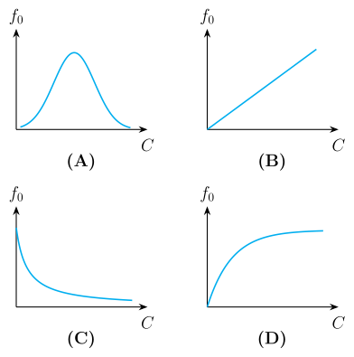
- KCET 2024Set D-21 markMCQQ.In an LCR series circuit, the value of only capacitance C is varied. The resulting variation of resonance frequency f0 as a function of C can be represented as
 (A)
(B)
(C)
(D)
(A)
(B)
(C)
(D)›Reveal solutionSolution
f0=2πLC1∝C−1/2: a monotonically decreasing, concave-up curve tending to zero.
Step 1 — Get the resonance condition.
In a series LCR circuit the impedance is
Z=R2+(XL−XC)2,XL=2πfL,XC=2πfC1.
Resonance is where Z is minimum, i.e. where the reactances cancel:
XL=XC⟹2πf0L=2πf0C1⟹f02=4π2LC1
f0=2πLC1
Step 2 — Isolate the dependence on C (the only quantity being varied).
f0=constant2πL1⋅C−1/2⟹f0∝C1.
Step 3 — Translate into the shape of the graph.
- f0 decreases as C increases (a bigger capacitor stores charge more readily, lowering the natural oscillation frequency).
- dCdf0=−21⋅2πL1C−3/2 — negative, and its magnitude shrinks as C grows, so the curve is steep at small C and flattens out. …
- COMEDK 2024Set 2024-E1 markMCQQ.A parallel plate capacitor having a dielectric constant 5 and dielectric strength 106 V m−1 is to be designed with voltage rating of 2 kV. The field should never exceed 10% of its dielectric strength. To have the capacitance of 60 pF the minimum area of the plates should be (A) 27.1×10⁻⁴ m2 (B) 2.7×10⁻² m2 (C) 2.71×10⁻⁴ m2 (D) 27.1×10⁻² m2
›Reveal solutionSolution
Cap the field at 10% of dielectric strength to fix the plate separation, then use C=dKε0A to solve for the area: A≈2.7×10⁻²m2.
Allowed field: E=10%×106=105V m−1.
Minimum plate separation for a 2kV rating:
d=EV=1052000=0.02m
Area from the capacitance C=dKε0A: …
- KCET 2023Set A-31 markMCQQ.A parallel plate capacitor of capacitance C1 with a dielectric slab in between its plates is connected to a battery. It has a potential difference V1 across its plates. When the dielectric slab is removed, keeping the capacitor connected to the battery, the new capacitance and potential difference are C2 and V2 respectively. Then, (A) V1>V2,C1>C2 (B) V1<V2,C1>C2 (C) V1=V2,C1>C2 (D) V1=V2,C1<C2
›Reveal solutionSolution
Battery still connected ⇒ V is fixed; removing the dielectric reduces C by the factor K.
Step 1 — What the battery fixes.
As long as the capacitor remains connected across the battery, the plates are held at the battery's emf. The potential difference cannot change:
V1=V2=ε.
This is the crux. (Contrast with the other standard version of this problem, where the battery is disconnected first — then the charge Q is what stays fixed and the voltage changes instead. Read which one the question states!)
Step 2 — What removing the dielectric does to C.
With a dielectric of constant K>1 filling the gap,
C1=KC0=dKε0A.
Remove the slab and it becomes an air-gap capacitor:
C2=C0=dε0A.
Since K>1,
C1=KC2>C2. …
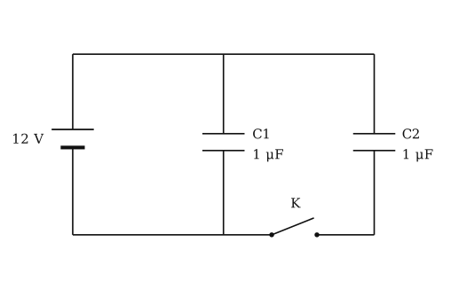
- COMEDK 2023Set 2023-E1 markMCQQ.In the figure, first the capacitors are fully charged by closing the key K. Then after opening the Key a dielectric material with dielectric constant 2 is filled in the space between the plates of both the capacitor. At this state the ratio of the Charge on the capacitor C1 to that of C2 is: (A) 1 : 1 (B) 3 : 2 (C) 2 : 1 (D) 1 : 2
›Reveal solutionSolution
Ratio Q1' : Q2' = 24 : 12 = 2 : 1.
Concept: a capacitor still connected to the battery keeps its VOLTAGE fixed (charge changes with C); an isolated capacitor keeps its CHARGE fixed (voltage changes).
From the figure: the 12 V cell, C1 and C2 all hang between the same top wire and the bottom wire, and the key K sits in the bottom wire BETWEEN the foot of C1 and the foot of C2. So C1 is permanently across the cell, while C2 completes its circuit only through K.
Stage 1 - K closed, both fully charged. Each capacitor sees the full 12 V:
Q1 = C1 V = 1 uF x 12 V = 12 uC
Q2 = C2 V = 1 uF x 12 V = 12 uC
Stage 2 - K opened. C2's lower plate is now disconnected, so C2 is ISOLATED and its charge is trapped at 12 uC. C1 remains connected across the 12 V cell. …
- COMEDK 2023Set 2023-M1 markMCQQ.A dielectric of dielectric constant K is introduced such that half of its area of a capacitor of capacitance C is occupied by it. The new capacity is (A) 2C (B) 2C (C) 2(1+K)C (D) 2C(1+K)
›Reveal solutionSolution
A dielectric filling half the plate area splits the capacitor into two parallel halves, one of area A/2 with air and one of area A/2 with the dielectric, giving C′=2(1+K)C.
The original capacitor: C=dε0A.
When a dielectric occupies half the area, the two halves act as capacitors in parallel (same plate separation d, each of area A/2): …
- KCET 2022Set B-31 markMCQQ.A parallel plate capacitor is charged by connecting a 2V battery across it. It is then disconnected form the battery and a glass slab is introduced between plates. Which of the following pairs of quantities decrease? (A) Energy stored and capacitance (B) Capacitance and charge (C) Charge and potential difference (D) Potential difference and energy stored.
›Reveal solutionSolution
Battery disconnected ⇒ Q is frozen; the dielectric raises C, so V=Q/C and U=Q2/2C both drop.
Step 1 — Identify what is held constant. This is the whole question.
There are two standard dielectric-insertion scenarios and they give opposite answers:
- Battery still connected ⇒ V is fixed (the battery enforces it), and Q=CV increases.
- Battery disconnected ⇒ the charge on the isolated plates has nowhere to go, so Q is fixed.
Here the capacitor is explicitly disconnected before the glass slab goes in, so
Q=constant
Step 2 — Capacitance.
A dielectric of dielectric constant K>1 (glass, K≈5–10) polarises and sets up an internal field opposing the applied one. The capacitance rises:
C=KC0=dKε0A(increases).
Step 3 — Potential difference.
V=CQ=KC0Q=KV0(decreases).
Physically: the polarised dielectric partially cancels the field between the plates, E=E0/K, and V=Ed, so V drops by the factor K. Starting from V0=2 V, the new p.d. is 2/K volts.
Step 4 — Energy stored.
With Q fixed, the convenient form of the energy is the one written in terms of Q and C:
U=2CQ2=2KC0Q2=KU0(decreases).
The "lost" energy is real: the slab is pulled in by the fringing field, so the field does positive work on it — energy leaves the capacitor. …
- KCET 2021Set B-21 markMCQQ.In the given arrangement of experiment on metre bridge, if AD corresponding to null deflection of the galvanometer is X, what would be its value if the radius of the wire AB is doubled? (A) X (B) 4X (C) 4X (D) 2X
›Reveal solutionSolution
The balance condition depends only on the ratio of the two lengths of AB, and thickening the wire cancels out of that ratio — so the null point does not move.
1. The concept — the metre bridge is a Wheatstone bridge.
The bridge wire AB (uniform, 1 m long) is tapped by a jockey at D. At the null point the galvanometer carries no current, so the Wheatstone condition holds:
SR=RDBRAD
where R and S are the resistances in the two gaps and RAD,RDB are the resistances of the two segments of the bridge wire.
2. Write the wire's resistance explicitly.
For a uniform wire of resistivity ρ, radius r and length ℓ:
RAD=πr2ρℓ,RDB=πr2ρ(100−ℓ)
3. Substitute — and watch r cancel.
SR=ρ(100−ℓ)/πr2ρℓ/πr2=100−ℓℓ
The resistivity ρ and the cross-sectional area πr2 cancel identically, because both segments are cut from the same wire. The balance condition therefore reduces to a pure ratio of lengths.
4. Apply the change. …
- KCET 2021Set B-21 markMCQQ.LC oscillations are similar and analogous to the mechanical oscillations of a block attached to a spring. The electrical equivalent of the force constant of the spring is (A) reciprocal of capacitive reactance (B) capacitive reactance (C) reciprocal of capacitance (D) capacitance
›Reveal solutionSolution
In an LC circuit, the electrical analogue of the spring constant k is the reciprocal of capacitance, 1/C, because both determine the restoring effect in their respective oscillations — the correct option is (C).
The key to this question is recognising the deep analogy between mechanical and electrical oscillations. A block on a spring oscillates because the spring provides a restoring force proportional to displacement: F=−kx. In an LC circuit, the charge on the capacitor oscillates because the capacitor provides a restoring "force" (voltage) proportional to charge: V=−Q/C. The minus sign indicates that the voltage always pushes charge back toward the equilibrium (zero charge). So the constant of proportionality here is 1/C, which plays the same role as k in the mechanical system.
Let’s walk through the analogy step by step to see why the other options don’t fit.
- Write the equations of motion side by side. For a mass m on a spring of constant k:
mdt2d2x=−kx
For an LC circuit (with inductance L and capacitance C):
Ldt2d2Q=−CQ
The form is identical: the coefficient in front of x (or Q) on the right-hand side is the "restoring coefficient."
-
Identify the analogous quantities.
Comparing the two equations:
- Mass m is analogous to inductance L (both store kinetic/magnetic energy and resist change in velocity/current).
- Displacement x is analogous to charge Q.
- The spring constant k is analogous to 1/C.
So the electrical equivalent of k is 1/C, not C itself.
-
Check the other options to confirm.
- Capacitive reactance XC=1/(ωC) depends on frequency ω, so it’s not a constant of the circuit like k is a constant of the spring. …
- KCET 2021Set B-21 markMCQQ.If a slab of insulating material (conceptual) 4×10⁻³ m thick is introduced between the plates of a parallel plate capacitor, the separation between the plates has to be increased by 3.5×10⁻³ m to restore the capacity to original value. The dielectric constant of the material will be (A) 6 (B) 8 (C) 10 (D) 12
›Reveal solutionSolution
A slab of thickness t and dielectric constant K acts like an air gap shortened by t(1−1/K); set that equal to the 3.5mm the plates were separated by.
Step 1 — Capacitance with a partially-filled gap.
For a parallel-plate capacitor of plate separation d containing a slab of thickness t and dielectric constant K (the rest being air):
C=d−t+Ktε0A
The reason: the slab's thickness t is removed from the air path and re-inserted as an electrically shorter length t/K, because the dielectric weakens the field inside it by the factor K.
Step 2 — Read off the "effective shortening".
Compare the denominator with the original air-only gap d:
deff=d−t+Kt=d−t(1−K1)
So the slab makes the gap behave as if it were shorter by t(1−K1), which is why the capacitance goes up when the slab is inserted.
Step 3 — Impose the restoring condition.
The plates are then moved apart by Δd=3.5×10⁻³m to bring C back to its original value. "Back to original" means the effective separation must once again equal d, so the increase must exactly cancel the shortening:
Δd=t(1−K1)
Step 4 — Substitute and solve. …
🎓Unlock everything free for 14 days
- ✓Full step-by-step solutions
- ✓Concept-first explanations
- ✓Methods, shortcuts & mistakes
- ✓PYQ mapping + timed mock tests
Full access for 14 days. No credit card required.