Q.In a circuit a 9 V cell is connected in the top line first to a capacitor C1=6 μF, then to a key K1, then to a key K2. A capacitor C2=3 μF joins the point between K1 and K2 down to the common return wire, and a capacitor C3=3 μF joins the point just beyond K2 down to the return wire, which goes back to the cell's negative terminal (take the unit capacitance C=1 μF, so C1=6 μF and C2=C3=3 μF). Initially K1 is closed and K2 is open — find the charge on each capacitor. Then K1 is opened and K2 is closed (the order is important) — find the new charge on each capacitor.
🔒You're viewing a preview — the full solution, concept, methods & PYQ mapping are locked.
🔒 Start your 14-day free trial to unlock the full solution →Concept understanding — Capacitor Network Analysis
Capacitor Network Analysis
Imagine you have a bucket of water and a pipe. The bigger the bucket, the more water it can hold for a given water pressure. A capacitor does the same thing with electric charge — it stores charge when a voltage is applied. The "size" of the bucket is called capacitance (C), measured in farads (F).
Now, what happens when you connect several buckets together with pipes? That's a capacitor network. The analysis is about finding one equivalent bucket (a single capacitor) that behaves exactly like the whole network.
The Core Idea: Charge and Voltage Must Match
When you connect capacitors, two things are always true:
- Charge conservation: Total charge in a closed part of the circuit stays the same unless a battery pushes more in.
- Voltage is shared: The voltage across each capacitor depends on how they're wired.
There are only two basic ways to connect them. Everything else is a combination of these two.
Series Connection: One Path, Shared Charge
Connect capacitors end-to-end, like train cars. The same current flows through each, so each capacitor stores the same amount of charge Q.
But the total voltage across the combination is the sum of the individual voltages:
Vtotal=V1+V2+V3+…
Since V=Q/C for each capacitor, we get:
CeqQ=C1Q+C2Q+C3Q+…
Cancel Q (it's the same everywhere):
Ceq1=C11+C21+C31+…
Intuition: Adding capacitors in series makes the equivalent capacitance smaller than the smallest individual one. Why? Because you're effectively making the "bucket" longer and narrower — harder to fill.
A common mistake: students treat series capacitors like series resistors (adding reciprocals for resistors, but adding directly for capacitors). It's the opposite. For resistors in series: Req=R1+R2. For capacitors in series: 1/Ceq=1/C1+1/C2.
Parallel Connection: Multiple Paths, Same Voltage
Connect capacitors side by side, like buckets with their bottoms connected by a wide pipe. Each capacitor sees the same voltage V across it.
But the total charge stored is the sum of charges on each:
Qtotal=Q1+Q2+Q3+…
Since Q=CV for each:
CeqV=C1V+C2V+C3V+…
Cancel V:
Ceq=C1+C2+C3+…
Intuition: Adding capacitors in parallel makes the equivalent capacitance larger — you're just adding more bucket area. Easy to fill.
| Connection | Equivalent Formula | What happens to Ceq |
|------------|-------------------|----------------------------------|
| Series | 1/Ceq=∑1/Ci | Gets smaller than smallest |
| Parallel | Ceq=∑Ci | Gets larger than largest |
How to Analyze Any Network
- Spot the pattern: Look for capacitors that are clearly in series (only two terminals, no branching between them) or clearly in parallel (both ends connected together).
- Replace step by step: Replace each simple series or parallel group with its equivalent capacitor. Redraw the circuit after each step.
- Repeat until you have one capacitor.
This is exactly like simplifying resistor networks — but with the reciprocal formula for series. If you can do resistor networks, you can do capacitor networks. Just flip the series formula.
A Worked Example
Suppose you have three capacitors: C1=2 μF, C2=3 μF, C3=6 μF. C2 and C3 are in parallel, and that combination is in series with C1. …
Phase 1: C1 (6 μF) and C2 (3 μF) are in series across 9 V, giving 18 μC on each, while C3 is isolated (0). Phase 2: C1 keeps its 18 μC; C2 and C3 become parallel and share C2's 18 μC equally, 9 μC each. …
With K1 closed and K2 open, C1 and C2 are in series across the 9 V cell, each holding 18 μC, while C3 is disconnected and holds nothing. Opening K1 traps C1's 18 μC; closing K2 places the charged C2 in parallel with the empty C3, so they share the 18 μC as 9 μC each.
Concept
Capacitors in series carry equal charge; capacitors in parallel share a common voltage. An isolated capacitor keeps its charge, and a group of connected isolated capacitors conserves total charge.
Phase 1 — K1 closed, K2 open
- Charging path: cell →C1→(K1)→C2→ back to cell. So C1=6 μF and C2=3 μF are in series across 9 V.
- Cseries=C1+C2C1C2=6+36×3=2 μF.
- Q=Cseries×E=2 μF×9 V=18 μC. Series ⇒ each of C1 and C2 carries 18 μC (with V1=18/6=3 V and V2=18/3=6 V, summing to 9 V).
- K2 open ⇒C3 is disconnected ⇒Q3=0.
Phase 2 — K1 opened, then K2 closed
- Opening K1 isolates C1's inner plate, so its 18 μC is trapped and unchanged: Q1=18 μC. …
Method: Analysing Capacitor Networks That Change with Switches
Use this for circuits where opening/closing keys changes which capacitors are connected to the cell and to each other — a very common exam pattern.
Steps
Step 1: Redraw (or re-imagine) the circuit separately for each switch configuration
Don't try to reason about the whole multi-phase problem at once. For each distinct state of the keys, trace which components are actually joined into a single conductive path, and identify whether that path includes the EMF source.
Step 2: Classify each connected group as series, parallel, or isolated
- Series (same charge flows through each): capacitors connected end-to-end with no other path branching off between them.
- Parallel (same voltage across each): capacitors whose corresponding terminals are tied directly together.
- Isolated: a capacitor whose plate has no closed path back to the rest of the circuit — it cannot exchange charge with anything, so whatever charge it was holding stays exactly as is.
Step 3: Solve the phase that's connected to the cell using Q=CV
Find the equivalent capacitance of the group actually connected to the EMF (series: Ceq1=∑Ci1; parallel: Ceq=∑Ci), then Qeq=Ceq×E. For a series group, every capacitor in it carries this same Qeq.
Step 4: When the switches change, track trapped charge vs. newly available charge …
Showing the 12 most recent of 19 on this concept.
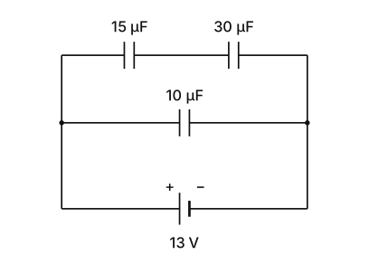
- COMEDK 2026Set 2026-M1 markMCQQ.What is the charge on 15μF in the circuit given? (A) 260μC (B) 230μC (C) 160μC (D) 130μC
›Reveal solutionSolution
The key is to find the voltage across the 15 µF capacitor by first computing the equivalent capacitance of the series branch, then using charge conservation and the fact that parallel branches share the same voltage. The charge on the 15 µF capacitor is 130 µC, which corresponds to option (D).
Concept & Intuition
When capacitors are in series, they each store the same charge (because the charge on one plate comes from the adjacent plate of the next capacitor). When branches are in parallel, they share the same voltage across their endpoints. Here, the 15 µF and 30 µF are in series, forming one branch; that branch is in parallel with the 10 µF capacitor. The battery supplies 13 V across both parallel branches. So we first find the equivalent capacitance of the series pair, then the charge on that equivalent capacitor — which is exactly the charge on each of the series capacitors. That gives us the charge on the 15 µF directly.
Step-by-step solution
- Identify the series combination The upper branch has a 15 µF and a 30 µF capacitor in series. For capacitors in series, the reciprocal of the equivalent capacitance is the sum of the reciprocals:
Ceq,series1=151+301=302+301=303=101
So Ceq,series=10 μF.
-
Interpret the parallel structure
This 10 µF equivalent capacitor (representing the 15 µF + 30 µF series branch) is in parallel with the 10 µF capacitor in the middle branch. Both are connected directly across the 13 V battery. Therefore, the voltage across the series branch is exactly 13 V.
-
Find the charge on the series branch
For any capacitor (or equivalent capacitor), Q=CV. The charge on the 10 µF equivalent capacitor is:
Qseries branch=(10 μF)×(13 V)=130 μC.
- Apply the series property …
- KCET 2026Set C21 markMCQQ.In the circuit shown in the figure
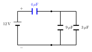 , the potential difference across the 4μF capacitor is
(A) 3 V
(B) 4 V
(C) 9 V
(D) 12 V
, the potential difference across the 4μF capacitor is
(A) 3 V
(B) 4 V
(C) 9 V
(D) 12 V›Reveal solutionSolution
In a series combination, every capacitor carries the same charge Q; use Q=CeqV for the whole combination, then V=Q/C for the capacitor in question.
Step 1 — Reduce the parallel combination
The 9μF and 3μF capacitors are in parallel:
Cparallel=9μF+3μF=12μF
Step 2 — Find the equivalent capacitance of the series combination
This 12μF is in series with the 4μF capacitor:
Ceq1=41+121=123+1=124⟹Ceq=3μF
Step 3 — Find the total charge supplied by the source
Q=CeqV=3μF×12V=36μC …
- COMEDK 2025Set 2025-A1 markMCQQ.By connecting two given capacitors, a technician was able to make two new capacitors having the effective capacitance 12.5μF and 2μF. What would be the capacitance of the given capacitors? (A) 8.5μ F and 4μ F (B) 10μ F and 2.5μ F (C) 6.5μ F and 6μ F (D) 10.5μ F and 2μ F
›Reveal solutionSolution
The problem involves two unknown capacitors that, when connected in series and in parallel, yield two specific effective capacitances. Solving the system of equations gives the individual capacitances as 10μF and 2.5μF, matching option (B).
The key idea is that connecting two capacitors in series and in parallel produces two distinct effective capacitances. The larger effective capacitance comes from the parallel combination (sum of the two), and the smaller from the series combination (reciprocal sum). By setting up and solving these two equations, we find the individual values.
-
Set up the equations.
Let the two unknown capacitances be C1 and C2 (in μF).
- In parallel: Cparallel=C1+C2=12.5
- In series: Cseries=C1+C2C1C2=2
-
Substitute the parallel sum into the series equation.
From the parallel equation, C1+C2=12.5.
Plug into the series equation:
12.5C1C2=2⇒C1C2=25
- Solve the system. We now have:
C1+C2=12.5,C1C2=25
These are the sum and product of the roots of the quadratic x2−(C1+C2)x+C1C2=0, i.e.,
x2−12.5x+25=0
Solve using the quadratic formula:
x=212.5±12.52−4⋅25=212.5±156.25−100=212.5±56.25
Since 56.25=7.5, we get:
x=212.5±7.5
So the two values are:
x1=220=10,x2=25=2.5 …
-
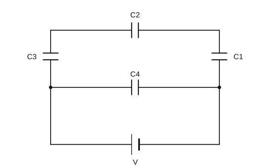
- COMEDK 2025Set 2025-E1 markMCQQ.A network of capacitors is as shown below. If the voltage supply is 100 V , find the energy stored in the 6μ F capacitor. C1=3μF,C2=6μF,C3=3μF and C4=4μF (A) 1.2 mJ (B) 12 mJ (C) 2.2 mJ (D) 4.2 mJ
›Reveal solutionSolution
C3,C2,C1 form a series string (=1.2 μF) that is in parallel with C4, so the full 100 V appears across the string. The common charge is 120 μC, giving VC2=20 V and stored energy 21C2VC22=1.2 mJ — option (A).
Concept
For capacitors in series the charge is common and voltages add; for capacitors in parallel the voltage is common and charges add. Energy stored in a capacitor is U=21CV2, using the voltage across that particular capacitor.
Step-by-step solution
- Series string. C3=3μF, C2=6μF, C1=3μF are in series:
Cs1=31+61+31=65 ⇒ Cs=1.2 μF.
- Voltage across the string. This string is connected in parallel with C4 directly across the supply, so it carries the full supply voltage:
Vs=100 V.
- Common charge. In the series string, …
- COMEDK 2025Set 2025-E1 markMCQQ.A capacitor of capacitance 4μ F is charged to a potential of 24 V and then connected in parallel to an uncharged capacitor of capacitance 6μ F. The final potential difference across each capacitor will be: (A) 6.9 V (B) 8.2 V (C) 9.6 V (D) 7.4 V
›Reveal solutionSolution
When a charged capacitor is connected in parallel to an uncharged one, charge redistributes until both share the same voltage. The final voltage is found by conserving total charge and using the equivalent parallel capacitance. The answer is 9.6 V.
Concept & Intuition
The key idea is charge conservation combined with the fact that in a parallel connection, both capacitors end up at the same potential difference. The total charge initially stored on the charged capacitor cannot go anywhere — it simply spreads across the two capacitors. Since the total capacitance in parallel is the sum of the individual capacitances, the final common voltage is just the initial charge divided by the total capacitance.
A common mistake is to think the voltage halves or follows some other simple ratio — but the correct ratio depends on the capacitances, not just the number of capacitors.
- Find the initial charge on the charged capacitor. The capacitor of 4μF is charged to 24V.
Qinitial=C1V=(4×10−6)×24=96×10−6C=96μC
-
Understand what happens when they are connected in parallel.
The uncharged 6μF capacitor initially has zero charge. When connected in parallel, charge flows from the charged capacitor to the uncharged one until the voltage across both is equal. The total charge in the system remains 96μC.
-
Find the equivalent capacitance of the parallel combination.
For capacitors in parallel, the total capacitance is the sum:
Ceq=C1+C2=4+6=10μF
- Calculate the final common voltage. …
- COMEDK 2025Set 2025-M1 markMCQQ.Two capacitors C1 and C2 are charged to 100 V and 120 V respectively. It is found that upon connecting them together in parallel, the potential on each one of them is zero. Therefore (A) C1+3C2=0 (B) 5C1=3C2 (C) 5C1+6C2=0 (D) 5C1=6C2
›Reveal solutionSolution
When two charged capacitors are connected in parallel and the final voltage is zero, the net charge on the combination must be zero. This gives the relation 5C1=6C2, so option (D) is correct.
Concept & Intuition
The key idea is conservation of charge. When capacitors are connected in parallel, the total charge before connection equals the total charge after connection. If the final voltage across both is zero, then the net charge on the combination must be zero. That means the positive charge on one capacitor exactly cancels the positive charge on the other — but careful: the sign of the charge depends on how they are connected. The problem implies they are connected so that the plates of opposite polarity are joined, leading to cancellation.
Step-by-step reasoning
- Initial charges Capacitor C1 is charged to 100V, so its charge is
Q1=C1×100=100C1.
Capacitor C2 is charged to 120V, so its charge is
Q2=C2×120=120C2.
-
Connection in parallel
When connected in parallel, the positive plate of one is joined to the negative plate of the other (this is the only way the final voltage can become zero — otherwise you'd just get a common nonzero voltage). So the charges are effectively opposite in sign relative to the connection.
-
Net charge after connection
The total charge on the combined system is
Qnet=Q1−Q2(if we take the polarity such that they oppose).
After connection, the final voltage is zero, meaning no net charge remains on the combination (since Q=CeqV and V=0 gives Q=0). Therefore
Q1−Q2=0⇒Q1=Q2. …
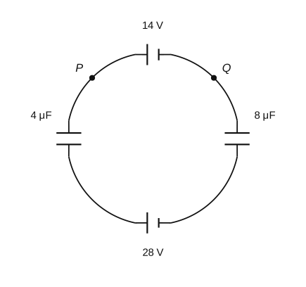
- COMEDK 2024Set 2024-A1 markMCQQ.The potential difference between the points P and Q of the arrangement shown in figure is (A) −9.3 V (B) 42 V (C) −42 V (D) −3.9 V
›Reveal solutionSolution
With the two capacitors in series and a net emf of 14 V, the common charge is ≈37.3μC; the resulting potential difference between P and Q is ≈−9.3 V.
In the steady state no current flows (capacitors block DC), and the 4μF and 8μF capacitors are in series around the loop.
Series capacitance:
Ceq=4+84×8=1232=38 μF.
Net driving emf (the two cells oppose): ε=28−14=14 V.
Common charge on each capacitor:
q=Ceqε=38×14=37.3 μC. …
- COMEDK 2024Set 2024-E1 markMCQQ.Figure below shows a network of resistors, cells, and a capacitor at steady state. What is the current through the resistance 4 Ω ? (A) 1.0 A (B) 0.2 A (C) Zero (D) 0.5 A
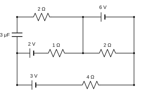
›Reveal solutionSolution
At steady state a capacitor is fully charged and carries no current, so its branch behaves as an open circuit and drops out of the current analysis. The remaining resistor–cell network then carries a single steady current, and applying Kirchhoff's voltage law gives the current through the 4 Ω resistor as 0.2 A. The correct option is (B).
Concept & Intuition
The decisive idea is that a capacitor in DC steady state acts as an open circuit: once it is fully charged, no more charge flows onto its plates, so no current passes through the branch that contains it. That branch can be removed for the purpose of finding currents; the capacitor's only remaining role is to hold a fixed steady voltage across itself. With the capacitor branch open, the rest of the network reduces to a simple current-carrying loop, and Kirchhoff's voltage law (KVL) determines the current.
Step-by-step reasoning
-
Open the capacitor branch. At steady state the capacitor is fully charged, so the branch containing it carries zero current. Remove it from the current analysis; it no longer provides a path for charge to flow.
-
Reduce the network. With that branch open, the remaining cells and resistors form a single conducting loop. The current is the same through every element in series along this loop, including the 4 Ω resistor.
-
Apply Kirchhoff's voltage law. Going once around the surviving loop, the sum of the EMFs equals the sum of the potential drops across the resistors:
∑E=I∑R
The net driving EMF of the loop, divided by its total series resistance, gives
-
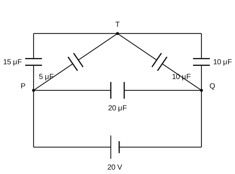
- COMEDK 2024Set 2024-E1 markMCQQ.The figure shows a network of five capacitors connected to a 20 V battery. Calculate the charge acquired by each 10 μF capacitor. (A) 2×10⁻⁴C (B) 4×10⁻⁴C (C) 6×10⁻⁴C (D) 1×10⁻⁴C
›Reveal solutionSolution
The two 10 µF capacitors share node T–Q, across which 10 V appears (equal series split of the 20 V), giving each Q=10μF×10V=1×10⁻⁴ C.
Label the top wire node T, left mid-node P, right mid-node Q; the 20 V battery is across P–Q.
- Between T and P: 15 µF (left branch) parallel with 5 µF (diagonal) =20 μF.
- Between T and Q: 10 µF (right branch) parallel with 10 µF (diagonal) =20 μF.
The path P→T→Q is these two 20 µF groups in series. The 20 µF direct branch (P–Q) simply sits across the battery and does not change the voltage split of the P–T–Q path. …
- COMEDK 2024Set 2024-M1 markMCQQ.A parallel plate capacitor is filled by a dielectric whose relative permittivity varies with the applied voltage (U) as ϵ=2U. A similar capacitor with no dielectric is charged to U0=78 V. It is then connected to the uncharged capacitor with the dielectric. Find the final voltage on the capacitors. (A) 6V (B) 8V (C) 2V (D) 4V
›Reveal solutionSolution
Charge conservation with ϵ=2U gives 2U2+U−78=0⇒U=6 V.
Let C0 be the base (vacuum) capacitance. The first (plain) capacitor is charged to U0=78 V, storing Q0=C0U0.
After connection the two capacitors are in parallel and share the final voltage U:
- Plain capacitor: Q1=C0U
- Dielectric capacitor: capacitance =ϵC0=2UC0, so Q2=(2UC0)U=2C0U2
Charge is conserved: …
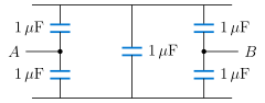
- KCET 2023Set A-31 markMCQQ.Five capacitors each of value 1μF are connected as shown in the figure. The equivalent capacitance between A and B is
 (A) 1μF
(B) 2μF
(C) 5μF
(D) 3μF
(A) 1μF
(B) 2μF
(C) 5μF
(D) 3μF›Reveal solutionSolution
A symmetry argument kills the middle capacitor (its two plates are at equal potential), leaving two identical series branches in parallel between A and B.
1. Label the four nodes
Call the top rail T and the bottom rail U. The five capacitors (all 1μF) connect:
A−T,A−U,B−T,B−U,T−U
(A is the mid-point of the left branch, B the mid-point of the right branch.) This is a bridge network, and the middle capacitor T−U is the bridge element.
2. The symmetry (the balanced-bridge condition)
Suppose we apply a potential difference between A and B. Now interchange the labels T↔U: the capacitor list maps to itself (A−T↔A−U, B−T↔B−U, and T−U to itself), and the terminals A, B are untouched. Because every capacitor is the same 1μF, the circuit is identical under this swap, so T and U must sit at the same potential:
VT=VU=2VA+VB
Equivalently, the bridge is balanced: CTBCAT=CUBCAU(=1).
3. Remove the bridge capacitor …
- COMEDK 2023Set 2023-M1 markMCQQ.A capacitor of capacity 2 μF is charged upto a potential 14 V and then connected in parallel to an uncharged capacitor of capacity 5 μF. The final potential difference across each capacitor will be (A) 6 V (B) 4 V (C) 8 V (D) 14 V
›Reveal solutionSolution
Conserving charge 28μC across the combined capacitance 7μF gives a common potential of 4 V.
Initial charge on the 2μF capacitor:
Q=C1V1=2μF×14V=28μC. …
🎓Unlock everything free for 14 days
- ✓Full step-by-step solutions
- ✓Concept-first explanations
- ✓Methods, shortcuts & mistakes
- ✓PYQ mapping + timed mock tests
Full access for 14 days. No credit card required.