Q.Explain with a circuit diagram, how a galvanometer can be converted into voltmeter.
You're viewing a preview — the full solution, concept, methods & PYQ mapping are locked.
Start your 14-day free trial to unlock the full solution →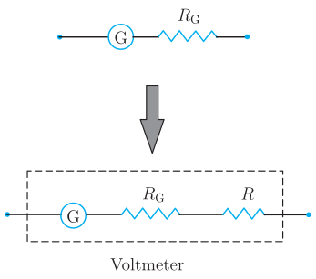
A galvanometer is converted into a voltmeter by connecting a high resistance () in series with it. This resistance limits the current so that full-scale deflection corresponds to the maximum voltage to be measured, and makes the meter's resistance very high so it draws negligible current from the circuit.
Explanation:
A galvanometer detects small currents and has a small resistance ; it gives full-scale deflection for a small current . To measure a potential difference up to , a high resistance is connected in series with the galvanometer.
Circuit: The galvanometer (coil resistance ) and the high series resistance are joined end to end, and this series combination is connected across the two points whose potential difference is to be measured. (A high resistance in series with the galvanometer, connected across the circuit element.)
For full-scale deflection, the current through the galvanometer is , and the total voltage across the combination is . Applying Ohm's law to the series path:
Solving for the required series resistance: …
Unlock everything free for 14 days
- Full step-by-step solutions
- Concept-first explanations
- Methods, shortcuts & mistakes
- PYQ mapping + timed mock tests
Full access for 14 days. No credit card required.