Q.With the help of a circuit diagram, explain how to convert a galvanometer into a voltmeter.
🔒You're viewing a preview — the full solution, concept, methods & PYQ mapping are locked.
🔒 Start your 14-day free trial to unlock the full solution →Concept understanding — Galvanometer to Voltmeter Conversion
Galvanometer to Voltmeter Conversion
A moving-coil galvanometer deflects fully only at a small current Ig (its full-scale deflection current) and has internal resistance G. To use it as a voltmeter — reading much larger voltages V — a large resistance Rs (the multiplier) is connected in series with the galvanometer coil. This series resistance limits the current to exactly Ig when the full-scale voltage V is applied, so the needle deflects fully and the scale is recalibrated to read volts instead of amperes.
The Conversion Formula
The galvanometer and Rs together form a series circuit of total resistance Rs+G. Applying V across this series combination drives a current
I=Rs+GV
We want this current to equal Ig exactly when V is the maximum (full-scale) voltage, so Ig=Rs+GV, which rearranges to:
Rs=IgV−G
Since the coil's deflection is proportional to the current through it, and that current is proportional to the applied voltage (Ohm's law), the resulting scale is linear in V: equal voltage steps give equal angular deflections.
Why series, not parallel?
A voltmeter must be connected across the component whose voltage is being measured, without diverting current away from it — so it should draw as little current as possible, meaning its own resistance must be as large as possible. Adding Rs in series does exactly that: it raises the meter's total resistance to Rs+G, which is deliberately made large. (This is the opposite requirement to an ammeter, which sits in the current path and needs the smallest possible resistance — achieved there with a small shunt in parallel, not a large resistor in series.)
Worked Example
For Ig=1 mA, G=50 Ω, converting to a 0–10 V voltmeter:
Rtotal=IgV=0.00110=10,000 Ω⟹Rs=10,000−50=9,950 Ω
A 9.95 kΩ resistor in series gives full-scale deflection at exactly 10 V.
Do not forget to subtract G from V/Ig. For most galvanometers G is small next to Rs, but in precision work it matters.
Key Properties
- High input resistance: Rv=Rs+G is large (kΩ to MΩ), so the voltmeter draws minimal current and barely disturbs the circuit it measures.
- Linear scale: deflection ∝ current ∝ voltage. …
A voltmeter must have a very high resistance so that, connected in parallel, it draws negligible current; a galvanometer alone has low resistance and a small full-scale current I_g. Adding a large series resistance R fixes this, with R chosen so the full-scale voltage V appears across the combination. …
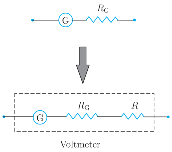
A galvanometer is converted into a voltmeter by connecting a suitable high resistance R in series with it. For full-scale voltage V, R=IgV−G.
Conversion of a galvanometer into a voltmeter:
A voltmeter is a high-resistance instrument connected in parallel across the two points whose potential difference is to be measured. A galvanometer has low resistance and can carry only a small current Ig (its full-scale deflection current). To measure a large voltage V, a high resistance R is connected in series with the galvanometer.
Circuit diagram (description): The galvanometer (coil resistance G) is joined in series with a large resistance R; this combination is connected across the two points A and B whose potential difference is being measured.
Value of the series resistance:
When the full-scale current Ig flows, the total voltage across the combination is …
- CBSE 2026Set ANNUAL1 markQ.The deflection per unit voltage in a voltmeter is called ______.
›Reveal solutionSolution
This ratio (deflection / voltage) is called the voltage sensitivity of the instrument.
A voltmeter is a galvanometer connected in series with a high resistance. Its voltage sensitivity is defined as the deflection theta produced per unit voltage V applied across it, i.e. voltage sensitivity = th …
- CBSE 2024Set 55/5/11 markMCQQ.A galvanometer of resistance 50Ω is converted into a voltmeter of range (0–2V) using a resistor of 1.0kΩ. If it is to be converted into a voltmeter of range (0–10V), the resistance required will be ______. (A) 4.8kΩ (B) 5.0kΩ (C) 5.2kΩ (D) 5.4kΩ
›Reveal solutionSolution
A galvanometer becomes a voltmeter by adding a high resistance in series; the same full-scale deflection current must flow in both configurations, so we first find Ig from the 2V setup, then calculate the series resistance needed for 10V. The answer is (C) 5.2kΩ.
Why a galvanometer needs a series resistor to measure voltage
A galvanometer is fundamentally a current-measuring device. Its coil deflects fully when a specific current Ig (the full-scale deflection current) flows through it. To measure voltage instead, we exploit Ohm's law: place a large resistance R in series with the galvanometer so that when the desired maximum voltage V appears across the combination, exactly Ig flows through the circuit.
The total resistance (G+R) and the voltage V are related by:
V=Ig(G+R)
where G is the galvanometer resistance. The key insight is that Ig and G are fixed properties of the galvanometer—they don't change when we reconfigure the circuit.
Step-by-step solution
1. Extract the full-scale deflection current from the first configuration
When the galvanometer is converted to a (0–2V) voltmeter using R1=1.0kΩ=1000Ω in series:
2=Ig(50+1000)
Ig=10502=5251A
This current is an intrinsic property of the galvanometer. Any voltmeter configuration must respect this same Ig for full-scale deflection.
2. Determine the series resistance for the (0–10V) range
For the new voltmeter to read up to 10V, the same current Ig must flow when 10V is applied. Let the required series resistance be R2:
10=Ig(G+R2) …
- CBSE 2024Set ANNUAL1 markQ.To convert a galvanometer into a voltmeter a resistance of __________ value is connected in series to it.
›Reveal solutionSolution
Adding a large series resistance limits the current through the galvanometer coil and extends the range so it can measure large potential differences directly.
A galvanometer is a sensitive instrument that gives full-scale deflection for only a very small current, and it has some small internal (coil) resistance G. To use it as a voltmeter capable of reading a potential difference V, a high resistance R is connected in series with it, chosen so that:
V=Ig(G+R)
…
- CBSE 2023Set B1 markQ.How is Galvanometer changed into a voltmeter?
›Reveal solutionSolution
Connecting a high resistance in series with a galvanometer converts it into a voltmeter of the desired range.
A galvanometer alone can only detect small currents and has a small, fixed full-scale voltage rating (since its coil has resistance G). To use it as a voltmeter capable of measuring a chosen larger range of potential difference V, a high resistance R is connected in series with the galvanometer coil, so that at full-scale deflection current Ig, V=Ig(G+R), giving R=IgV−G. This series resistance both extends the voltage range and ensures the …
- CBSE 2022Set ANNUAL1 markQ.How can a galvanometer be converted into a voltmeter?
›Reveal solutionSolution
A galvanometer is converted into a voltmeter by putting a large resistance in series with it, so that most of the applied voltage drops across this resistance rather than across the (delicate, low-current) galvanometer coil.
A galvanometer of coil resistance G gives full-scale deflection for a small current Ig. To use it to measure a larger potential difference V across some element, we connect a high resistance R in series with the galvanometer. The combination (galvanometer + R) is then connected across the points whose voltage is to be measured. The value of R needed for the voltmeter to read up to V at full-scale deflection is found from: …
- CBSE 2019Set ANNUAL1 markMCQQ.To convert a galvanometer into a voltmeter, we must connect a(a) high resistance in parallel with the galvanometer(b) high resistance in series with the galvanometer(c) low resistance in parallel with the galvanometer(d) low resistance in series with the galvanometer
›Reveal solutionSolution
A voltmeter needs high internal resistance so it draws minimal current, and is inserted in parallel with the element being measured — this is achieved by adding a large series resistance to the galvanometer.
Reasoning
A voltmeter is connected in parallel across the component whose voltage is to be measured. For it to disturb the circuit as little as possible, it must draw very little current — i.e. it must have a very high resistance overall. This is achieved by connecting a high resistance R in series with the galvanometer coil; the combination then has resistance G+R≈R (large), and a known fraction of the potential dif …
- CBSE 2019Set ANNUAL1 markMCQQ.To convert a galvanometer into a voltmeter, we connect with it a :(a) high resistance in series(b) low resistance in parallel(c) low resistance in series(d) high resistance in parallel
›Reveal solutionSolution
A galvanometer is converted into a voltmeter by connecting a high resistance in series with it.
A galvanometer is a sensitive instrument that gives full-scale deflection for a very small current, and it has a small resistance G. A voltmeter must:
- Draw only a small current from the circuit across which it measures the potential difference (so it doesn't disturb the circuit).
- Have as HIGH a resistance as possible so that it draws negligible current.
To achieve this, a high resistance R is connected in SERIES with the galvanometer. If Ig is the full-scale deflection current of the galvanometer and V is the voltmeter range to be measured, then …
🎓Unlock everything free for 14 days
- ✓Full step-by-step solutions
- ✓Concept-first explanations
- ✓Methods, shortcuts & mistakes
- ✓PYQ mapping + timed mock tests
Full access for 14 days. No credit card required.