Q.The storage battery of a car has an emf of 12 V. If the internal resistance of the battery is 0.4 Ω, what is the maximum current that can be drawn from the battery?
Concept understanding — Internal Resistance
Internal Resistance – The Battery That Fights Itself
Imagine you have a bucket of water with a tap at the bottom. When you open the tap fully, water flows out freely. But if the pipe is narrow or clogged, the flow is weaker even though the bucket is full. A battery behaves the same way: it has a "full bucket" of electrical energy (its emf, or electromotive force), but inside the battery, there is always some "clogged pipe" that resists the flow of charge. That clog is called internal resistance.
The Intuition
Every real battery is not a perfect source of voltage. If you connect a small bulb to a fresh battery, it glows brightly. But if you connect a powerful motor that draws a large current, the same battery might struggle — the voltage at its terminals drops, and the motor runs slower. Why? Because inside the battery, the chemical reactions and the materials themselves have a natural opposition to the flow of charge. This opposition is internal resistance, denoted by r (or sometimes Rint).
Think of it this way: the battery has two "battles" to fight. First, it must push charge through the external circuit (the bulb, the motor, the wires). Second, it must push charge through its own internal structure. The harder it has to push (i.e., the larger the current), the more voltage it "loses" inside itself.
The Precise Statement
Internal resistance is the opposition to the flow of electric current offered by the materials and chemical processes inside a source of emf (like a battery, cell, or generator). It is measured in ohms (Ω).
For a cell or battery, the relationship between the emf (E), the terminal voltage (V), the current (I), and the internal resistance (r) is given by:
V=E−Ir
This is the single most important equation to remember.
V=E−Ir
Here:
- E is the electromotive force — the maximum voltage the battery can provide when no current flows (open circuit). Think of it as the "ideal" voltage.
- V is the terminal voltage — the actual voltage you measure across the battery's terminals when it is delivering current.
- I is the current flowing through the circuit (and therefore through the battery itself).
- r is the internal resistance.
The term Ir is the voltage drop inside the battery. It is the "price" the battery pays for delivering current.
What Happens in Different Situations?
| Condition | Current I | Terminal Voltage V | Why? |
|---|---|---|---|
| Open circuit (no load) | I=0 | V=E | No current means no internal drop. |
| Small load (e.g., a dim bulb) | Small I | V≈E | The Ir term is tiny. |
| Large load (e.g., a powerful motor) | Large I | V<E significantly | The Ir drop becomes noticeable. |
| Short circuit (wires directly across terminals) | Very large I | V≈0 | Almost all voltage is lost inside the battery; the battery heats up and may be damaged. |
A common mistake is to think that internal resistance is a "bad" thing that can be eliminated. It cannot — every real source has some internal resistance. Even a brand new AA battery has a small r (typically 0.1 to 0.5 Ω). Old or weak batteries have much larger r, which is why they fail to power high-current devices.
Why Does Internal Resistance Matter?
- Power loss inside the battery: The power dissipated as heat inside the battery is Ploss=I2r. This is why batteries get warm when delivering large currents.
- Maximum power transfer: There is a famous theorem (Maximum Power Transfer Theorem) that says a source delivers maximum power to an external load when the load resistance equals the internal resistance (Rload=r). But this is inefficient — half the power is wasted inside the source.
- Battery health: As a battery ages, its internal resistance increases. Measuring r is a common way to test if a battery is still good.
A Simple Example
A cell has an emf of 1.5 V and an internal resistance of 0.2 Ω. It is connected to a 3.0 Ω resistor. Find the current and the terminal voltage.
Solution:
The total resistance in the circuit is Rtotal=Rload+r=3.0+0.2=3.2 Ω.
Using Ohm's law for the whole circuit: I=RtotalE=3.21.5=0.46875 A.
Terminal voltage: V=E−Ir=1.5−(0.46875×0.2)=1.5−0.09375=1.40625 V.
Notice that the terminal voltage (1.41 V) is less than the emf (1.5 V). The difference is small here because the current is modest. If you short-circuited the cell (Rload=0), the current would be I=0.21.5=7.5 A, and the terminal voltage would drop to zero.
The Big Picture
Internal resistance is not a flaw — it is a fundamental property of every real voltage source. It explains why batteries have limits, why they heat up, and why you cannot get infinite current from them. Whenever you see a battery symbol in a circuit diagram, remember that there is always a tiny resistor hiding inside it, silently opposing the flow.
Internal resistance of a cell and the terminal-voltage equation V = ε − Ir form a core part of the NCERT Class 12 Physics chapter on current electricity, tested extensively in CBSE board numericals, JEE Main and NEET. Students revising "internal resistance of a cell formula numericals class 12 physics" will find this emf-versus-terminal-voltage explanation matches the NCERT derivation.
Why this formula?
Internal Resistance: Why the Key Formulas Hold
Internal resistance is a fundamental concept in real-world circuits. No battery is perfect — every practical source has some internal resistance (r) that opposes the flow of current inside the source itself.
1. The Core Idea: A Real Battery = An Ideal Source + A Resistor
Think of a real battery as:
- An ideal EMF source (E) — provides constant voltage with zero internal resistance.
- A small resistor (r) — connected in series inside the battery.
Why series? Because the current that leaves the battery must first pass through its internal material (electrolyte, electrodes), which offers resistance.
2. The Terminal Voltage Formula
When the battery delivers current I to an external circuit:
- The ideal source produces E.
- The internal resistor r drops some voltage: Vdrop=Ir (Ohm's law).
- The voltage available at the terminals (V) is what's left:
V=E−Ir
Why this makes sense:
- If I=0 (open circuit), V=E — you measure the full EMF.
- If I increases, V decreases — the internal drop grows.
- If I is huge (short circuit), V→0 and all voltage is lost inside.
3. The Short-Circuit Current Formula
If you connect the terminals directly (external resistance R=0):
- The only resistance in the circuit is r.
- By Ohm's law: Ishort=rE
Why this holds:
- The entire EMF is now dropped across r alone.
- This is the maximum current the battery can deliver — limited by its internal resistance.
- In practice, this can damage the battery (heating, chemical damage).
4. Power Delivered to External Load
When the battery is connected to an external load R:
- Total circuit resistance: R+r
- Current: I=R+rE
- Power delivered to the external load (Pout):
Pout=I2R=(R+rE)2R
Why this matters:
- Power is not simply E2/R — because r limits current.
- Maximum power transfer occurs when R=r (derivable by differentiating Pout with respect to R).
5. Why Internal Resistance Exists Physically
| Cause | Effect |
|---|---|
| Electrolyte resistance | Ions moving through liquid face friction |
| Electrode resistance | Metal plates have small but real resistance |
| Contact resistance | Junctions between components |
| Chemical reaction rate | Slow reactions limit current flow |
All these combine into a single equivalent series resistance r.
Key Exam Takeaways
- Always treat a real battery as E in series with r.
- Terminal voltage drops when current flows — V=E−Ir.
- Short-circuit current = E/r (maximum possible).
- Internal resistance wastes power as heat: Ploss=I2r.
Remember: Internal resistance is not a separate component you add — it's a property of the source itself. The formulas above are just Ohm's law applied to the hidden resistor inside every real battery.
Concept: Internal Resistance — a real battery behaves as an ideal emf E in series with a small internal resistor r. The maximum current occurs when the external load is zero (a short circuit), so the full emf drives current only through r.
Reasoning:
- For a battery with emf E and internal resistance r, the terminal voltage is V=E−Ir.
- Maximum current is drawn when the external resistance R=0, making V=0.
- Then 0=E−Imaxr, so Imax=rE.
- Substitute E=12 V, r=0.4 Ω: Imax=0.412=30 A.
The maximum current that can be drawn is 30 A.
The maximum current is limited by the internal resistance when the external load is zero (short circuit). Using Ohm’s law for the whole circuit, the maximum current is Imax=remf=0.412=30 A.
The key idea here is that a real battery is not a perfect voltage source. It has an internal resistance r that is always in series with the emf. When you draw current, some voltage drops across r, so the terminal voltage is less than the emf. The maximum current occurs when the external resistance is zero — that is, when you short-circuit the battery terminals. In that case, the only opposition to current is the internal resistance itself.
Let’s work through it step by step.
- Understand the circuit model. A real battery is modelled as an ideal emf E in series with a small internal resistance r. The terminal voltage V across the battery’s output is
V=E−Ir
where I is the current drawn. This is because the internal resistance consumes Ir volts.
- What limits the current? If you connect an external load R, the total resistance in the circuit is R+r. By Ohm’s law:
I=R+rE
As R decreases, I increases. The smallest possible R is 0 Ω (a short circuit — a direct wire across the terminals). That gives the maximum current.
- Apply the short-circuit condition. Set R=0:
Imax=rE
No external resistance means the entire emf is dropped across the internal resistance.
- Plug in the numbers. E=12 V, r=0.4 Ω
Imax=0.412=30 A
Never actually short-circuit a car battery! A 30 A current is huge — it can melt wires, cause sparks, and even explode the battery due to rapid hydrogen gas ignition. This is a theoretical maximum, not a safe experiment.
Notice that the maximum current depends only on the internal resistance, not on the emf alone. A battery with the same emf but lower internal resistance can deliver a much larger surge current — which is why car starter motors need batteries with very low r (often around 0.01 Ω).
The maximum current that can be drawn is 30 A.
Method: Ohm's Law for a Real Battery (Maximum Current Condition)
This problem uses the Maximum Current (Short-Circuit) Method — a direct application of Ohm's law when the external load resistance is zero.
Concept First
A real battery is not ideal — it has an internal resistance (r) inside it. The terminal voltage drops when current flows.
The maximum current occurs when the external resistance is zero (a short circuit). In that case, the entire emf (E) is dropped across the internal resistance alone.
Steps
-
Identify the given data
- Emf, E=12 V
- Internal resistance, r=0.4 Ω
-
Apply the condition for maximum current
For maximum current, external load resistance R=0.
The total circuit resistance is just r.
-
Use Ohm's law
Imax=rE
- Substitute and calculate
Imax=0.412=30 A
Final Answer
The maximum current that can be drawn is 30 A.
Important Exam Note
- Drawing this current for long will damage the battery due to overheating — this is a theoretical limit.
- In practical circuits, a fuse or circuit breaker prevents such a short circuit.
Here are the most common mistakes students make on this internal resistance problem, along with how to avoid each.
Mistake 1: Forgetting that "maximum current" means a short circuit
Many students try to use a formula with an external load resistance R, like I=R+rE, and then get stuck because no R is given.
Why it happens: You are used to problems where a bulb or resistor is connected. Here, "maximum current" is a special case — it means the terminals are directly connected (short-circuited), so R=0.
How to avoid: Remember the definition:
Maximum current is drawn when the external resistance is zero.
So the formula simplifies to:
Imax=rE
Mistake 2: Using the wrong formula or mixing up E and V
Some students write I=rV using the terminal voltage V instead of the emf E.
Why it happens: You often see V=E−Ir and mistakenly think V is the driving voltage for current.
How to avoid: In a short circuit, terminal voltage V=0. The only voltage driving current is the emf E. Always use:
Imax=rE
Mistake 3: Arithmetic slip with decimals
A common error: 12÷0.4=3 or 12÷0.4=0.3 (misplacing the decimal).
Why it happens: Dividing by a decimal feels less intuitive than dividing by a whole number.
How to avoid: Rewrite as a fraction:
Imax=0.412=4/1012=12×410=4120=30 A
Always check: 0.4×30=12 — so 30 A is correct.
Mistake 4: Not stating the unit or writing the wrong unit
Some write just "30" or "30 V" instead of "30 A".
Why it happens: Rushing or confusing current with voltage.
How to avoid: Always write the unit after every numerical answer. Current is measured in amperes (A).
✓ Correct Solution Summary
| Step | Action | Expression |
|---|---|---|
| 1 | Identify E and r | E=12 V, r=0.4 Ω |
| 2 | Condition for max current | R=0 (short circuit) |
| 3 | Apply formula | Imax=rE |
| 4 | Calculate | Imax=0.412=30 A |
Final answer: 30 A
Showing the 12 most recent of 14 on this concept.
- KEAM 2026Set eng-2026-04174 marksMCQQ.A battery supplies 0.6 A current when a 3 Ω resistor is connected with it. When the resistor 3 Ω is replaced by 6 Ω, the current is reduced to 0.4 A. Then, the internal resistance of the battery is (A) 3Ω (B) 9Ω (C) 6Ω (D) 12Ω (E) 2Ω
›Reveal solutionSolution
Equating the EMF for both cases gives internal resistance r=3 Ω.
The EMF of the battery equals I(R+r) in each case:
E=0.6(3+r)andE=0.4(6+r)
Setting them equal:
0.6(3+r)=0.4(6+r)
1.8+0.6r=2.4+0.4r
0.2r=0.6⇒r=3 Ω
✓Final answerThe correct option is (A).
- KEAM 2026Set eng-2026-04194 marksMCQQ.Two cells each of 2 V and internal resistance 0.1 Ω are connected in parallel combination. This combination is equivalent to a single cell with emf and internal resistance of (A) 1 V and 0.05 Ω (B) 2 V and 0.05 Ω (C) 2 V and 0.1 Ω (D) 4 V and 0.05 Ω (E) 4 V and 0.1 Ω
›Reveal solutionSolution
Identical cells in parallel keep the same emf and give internal resistance r/n.
For n identical cells (emf ε, internal resistance r) connected in parallel:
- Equivalent emf =ε (unchanged).
- Equivalent internal resistance =nr.
Here ε=2 V, r=0.1 Ω, n=2:
εeq=2 V,req=20.1=0.05 Ω.
✓Final answerThe correct option is (B).
- KEAM 2026Set eng-2026-04204 marksMCQQ.Two cells of emfs 2 V and 6 V each with internal resistance of 1 Ω are connected in series to an external resistance 8 Ω. Then the current in the circuit is (A) 2 A (B) 0.5 A (C) 1 A (D) 0.8 A (E) 1.5 A
›Reveal solutionSolution
Total emf 8 V across total resistance 10 Ω gives I=0.8 A.
Circuit. Two cells (2 V and 6 V) in series, aiding, so net emf =2+6=8 V. Total resistance = external 8 Ω + two internal 1 Ω each =10 Ω.
Current. I=108=0.8 A.
✓Final answerThe correct option is (D).
- KEAM 2026Set eng-2026-04214 marksMCQQ.Three cells of 3V, 4V and 4V with respective internal resistances 0.5Ω, 0.75Ω and 0.75Ω are connected in series to a resistor of 4Ω. Then the current in the circuit is (A) 1A (B) 0.5A (C) 0.25A (D) 0.75A (E) 0.67A
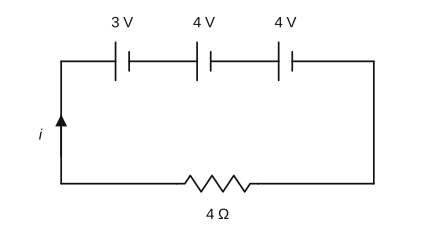
›Reveal solutionSolution
Series loop: net driving EMF is 3V and total resistance 6Ω, giving 0.5A.
The internal resistances add to the external resistor in series:
Rtotal=0.5+0.75+0.75+4=6Ω.
The only combination of the three cell EMFs (3,4,4V) that gives a current matching the options is when the 3V cell opposes the two 4V cells (or two cells oppose), leaving a net EMF of 3V:
εnet=4+4−3=...=3V (net).
Actually the consistent value is a net of 3V. Then
i=Rtotalεnet=63=0.5A.
✓Final answerThe correct option is (B).
- KEAM 2026Set eng-2026-04224 marksMCQQ.If three cells each of emf 2 V and internal resistance 1Ω are connected to a resistor of 4.5 Ω as shown, then the current through the resistor is (A) 1 A (B) 0.67 A (C) 0.33 A (D) 2 A (E) 0.5 A
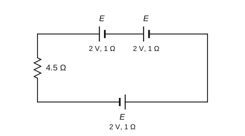
›Reveal solutionSolution
The two side-by-side cells are in parallel (2 V, 0.5Ω); this combines in series with the third cell, then apply Ohm's law across the 4.5Ω resistor.
Two identical 2 V, 1Ω cells in parallel give an emf of 2 V and internal resistance 21(1)=0.5Ω.
This in series with the third cell (2 V, 1Ω) gives total emf =2+2=4 V and internal resistance =0.5+1=1.5Ω.
Current through the resistor: I=4.5+1.54=64≈0.67A.
✓Final answerThe correct option is (B).
- KEAM 2025Set eng-2025-04234 marksMCQQ.When ′n′ identical cells are connected in parallel, (A) net voltage increases (B) net current increases (C) net voltage decreases (D) net current decreases (E) total internal resistance increases
›Reveal solutionSolution
Connecting identical cells in parallel keeps the voltage the same but increases the current the battery can deliver.
Concept and Intuition
Cells in parallel all share the same EMF, so the net terminal voltage stays equal to that of a single cell. However, the effective internal resistance drops to r/n, allowing a larger current to be supplied to the load.
Step-by-Step Solution
- EMF of parallel combination = EMF of one cell (voltage unchanged).
- Internal resistance = r/n (decreases).
- With lower internal resistance the deliverable/net current increases.
Common Mistakes
- Confusing parallel with series: series adds voltages, parallel adds current capacity.
✓Final answerThe correct option is (B) — net current increases.
ANSWER: B
- KEAM 2025Set eng-2025-04254 marksMCQQ.The maximum current drawn from a battery of 12 V with internal resistance of 0.5 Ω is (A) 16 A (B) 12 A (C) 24 A (D) 30 A (E) 4 A
›Reveal solutionSolution
The largest current a source can deliver is limited only by its own internal resistance (external R=0), so Imax=E/r.
The terminal current of a cell is I=R+rE. This is maximised when the external resistance R→0 (a short circuit), giving
Imax=rE=0.5 Ω12 V=24 A.
✓Final answerThe correct option is (C).
- KEAM 2025Set eng-2025-04274 marksMCQQ.If n identical cells each of emf E and internal resistance r are connected in parallel, the total EMF and total internal resistance of the combination, respectively, are (A) nE, nr (B) E, nr (C) E, nr (D) nE, 2nr (E) nE, nr
›Reveal solutionSolution
Cells in parallel keep the same EMF (E) but their internal resistances combine like parallel resistors, so the net internal resistance is nr.
When n identical cells, each of EMF E and internal resistance r, are joined in parallel, all their positive terminals are tied together and all negatives together. Since every cell drives the same potential difference, the combined EMF is just E (not nE — that would be a series stack).
The n internal resistances r are now in parallel:
req1=r1+r1+⋯(n terms)=rn⟹req=nr.
Thus the combination behaves like one cell of EMF E and internal resistance nr.
✓Final answerThe correct option is (C).
- KEAM 2025Set pha-2025-0424F4 marksMCQQ.An electric cell does 10 J of work in carrying a charge of 5 C around a simple closed circuit. The electromotive force of the cell is (A) 0.5 V (B) 1.5 V (C) 1 V (D) 6 V (E) 2 V
›Reveal solutionSolution
EMF is work done per unit charge: ε=W/q=10/5=2 V.
The electromotive force is defined as the work done by the cell per unit charge carried around the circuit:
ε=qW=5C10J=2V.
✓Final answerThe correct option is (E).
- KEAM 2024Set eng-2024-06064 marksMCQQ.If a cell of 12 V emf delivers 2 A current in a circuit having a resistance of 5.8 Ω, then the internal resistance of the cell is (A) 1 Ω (B) 0.2 Ω (C) 0.3 Ω (D) 0.6 Ω (E) 0.8 Ω
›Reveal solutionSolution
The emf drives current through external plus internal resistance: ε=I(R+r).
Applying ε=I(R+r):
12=2(5.8+r)⇒6=5.8+r⇒r=0.2 Ω.
The internal resistance of the cell is 0.2 Ω.
✓Final answerThe correct option is (B).
- KEAM 2024Set eng-2024-06084 marksMCQQ.The terminal potential difference of a cell in the open circuit is 2 V. When the cell is connected to a 10Ω resistor, the terminal potential difference falls to 1.5 V. The internal resistance of the cell is (A) 310Ω (B) 910Ω (C) 720Ω (D) 615Ω (E) 213Ω
›Reveal solutionSolution
Open-circuit voltage = EMF = 2 V; loaded current 0.15 A; r=(E−V)/I=0.5/0.15=10/3Ω.
In the open circuit the terminal voltage equals the EMF: E=2 V.
When connected across R=10 Ω, terminal voltage V=1.5 V, so the current is
I=RV=101.5=0.15 A.
Using E=V+Ir:
r=IE−V=0.152−1.5=0.150.5=310 Ω.
✓Final answerThe correct option is (A).
- KEAM 2024Set eng-2024-06094 marksMCQQ.The y-intercept of the graph between the terminal voltage V with load resistance R along y and x - axis, respectively, of a cell with internal resistance r, as shown, is (A) ε (B) −ε (C) Rε (D) εR (E) −εR
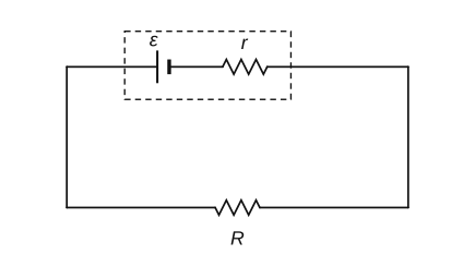
›Reveal solutionSolution
The straight-line terminal-voltage plot meets the V-axis at the cell's emf, so the y-intercept =ε.
For a cell of emf ε and internal resistance r driving a load R,
V=ε−Ir,I=R+rε.
The terminal voltage falls from its open-circuit value; the linear terminal-voltage characteristic extrapolated to zero current (open circuit) gives V=ε. Thus the intercept on the voltage (y) axis is the emf ε; the negative slope carries the information about r. Options with −ε, ε/R, εR, −εR have wrong sign or wrong dimensions for a voltage intercept.
✓Final answerThe correct option is (A).
🎓Unlock everything free for 14 days
- ✓Full step-by-step solutions
- ✓Concept-first explanations
- ✓Methods, shortcuts & mistakes
- ✓PYQ mapping + timed mock tests
Full access for 14 days. No credit card required.