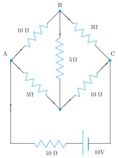
Q.Determine the current in each branch of the network shown in Fig. 3.20.
🔒You're viewing a preview — the full solution, concept, methods & PYQ mapping are locked.
🔒 Start your 14-day free trial to unlock the full solution →Concept understanding — Wheatstone Bridge Symmetry
Wheatstone Bridge Symmetry
Four resistors are arranged in a diamond. A battery sits across the top and bottom points; a sensitive galvanometer bridges the left and right points. The question is: when does no current flow through the galvanometer? The answer is symmetry.
The Intuition
Treat the bridge as two parallel voltage dividers — two resistors in series on the left, two in series on the right — with the galvanometer joining their midpoints. If both dividers produce the same midpoint voltage, there is no potential difference across the galvanometer and no current flows: the bridge is balanced. This happens when the resistance ratio on the left arm equals the ratio on the right arm.
Symmetry here means equal ratios, not equal resistances. 1 Ω with 2 Ω on one side balances 100 Ω with 200 Ω on the other.
The Precise Statement
Label the four resistors: R1 top-left, R2 bottom-left, R3 top-right, R4 bottom-right. The battery connects the top junction (between R1, R3) to the bottom junction (between R2, R4); the galvanometer connects the two midpoints. The bridge is balanced when
R2R1=R4R3
The balance condition is independent of the battery voltage and of the galvanometer's resistance — it depends only on the four resistor values.
Why This Matters
- Unknown resistance: put the unknown in place of R4, adjust the others until balanced, then R4=R3R1R2.
- Strain gauges: stretching slightly changes a resistance, unbalancing the bridge; the deflection measures the strain.
- Temperature sensors: a temperature-dependent resistor unbalances the bridge in proportion to the change. …
Why this formula?
Wheatstone Bridge Symmetry — Why the Formula Holds
The Wheatstone bridge is a circuit used to measure an unknown resistance by balancing two legs of a bridge. The key result is:
When the bridge is balanced, no current flows through the galvanometer, and:
R2R1=R4R3
Let's understand why this is true — not just memorize it.
1. The Circuit Setup
A Wheatstone bridge has four resistors arranged in a diamond:
- R1 and R2 in series on the left branch
- R3 and R4 in series on the right branch
- A galvanometer (sensitive current detector) connects the midpoints of the two branches
- A battery connects across the top and bottom
        A
       / \
      /   \
     R1    R3
     |     |
     G-----|   (G = galvanometer)
     |     |
     R2    R4
      \   /
       \ /
        B
2. The Condition for Balance — "No Current Through G"
Balance means the galvanometer shows zero deflection — no current flows through it. This implies points C (between R1 and R2) and D (between R3 and R4) are at the same electric potential. If VC=VD, no potential difference exists across the galvanometer, so no current flows.
3. Deriving the Ratio — Step by Step
Step 1: Branch currents
With no current through G, the left branch carries a single current I1 and the right branch a single current I2.
Step 2: Equal potentials at the midpoints
From A (common top) to the midpoints, since VC=VD:
I1R1=I2R3(1)
From the midpoints to B (common bottom), since VC=VD:
I1R2=I2R4(2)
Step 3: Divide (1) by (2)
I1R2I1R1=I2R4I2R3
The currents I1 and I2 cancel: …
Check the balance condition first. With arms AB=10 Ω, BC=5 Ω, AD=5 Ω, DC=10 Ω:
BCAB=510=2,DCAD=105=0.5.
These are unequal, so the bridge is unbalanced and current does flow through the 5 Ω bridge arm BD — the 'no current in the middle' shortcut does not apply.
Solving with mesh/Kirchhoff equations (the 10 V cell is in series with a 10 Ω resistor across A–C): a star–delta reduction of the bridge gives 7 Ω between A and C, so the total current is …
The network is an unbalanced Wheatstone bridge (arms AB=10 Ω, BC=5 Ω, AD=5 Ω, DC=10 Ω, bridge BD=5 Ω) fed by a 10 V cell in series with 10 Ω across A–C. The bridge presents 7 Ω, so the battery drives 1710 A≈0.59 A; the branch currents are 174,176,176,174 and 172 A.
The network. Nodes A (left), B (top), C (right), D (bottom) form a bridge: AB=10 Ω, BC=5 Ω, AD=5 Ω, DC=10 Ω, with a 5 Ω bridge arm BD. The supply is a 10 V cell in series with a 10 Ω resistor across A and C.
Is it balanced? BCAB=510=2 while DCAD=105=0.5; unequal, so the bridge is unbalanced and current flows in BD. We use mesh (loop) analysis.
Mesh equations. With clockwise mesh currents i1 (loop ABD), i2 (loop BCD), i3 (loop A-D-C-battery):
4i1−i2−i3=0,−i1+4i2−2i3=0,−i1−2i2+5i3=2.
Solving: i1=174, i2=176, i3=1710 A.
Branch currents.
| Branch | Element | Current |
|---|---|---|
| AB | 10 Ω | 174≈0.235 A |
| BC | 5 Ω | 176≈0.353 A |
| AD | 5 Ω | 176≈0.353 A |
| DC | 10 Ω | 174≈0.235 A |
Method: Mesh (Loop) Analysis for a Multi-Branch Resistor Network
Use this general technique to find every branch current in ANY resistor network with more than one loop — bridges, ladders, or arbitrary meshes — once you've confirmed no shortcut (symmetry, or a balanced-bridge condition) is available.
Steps
Step 1: Check for a shortcut first
Always check whether the network has exploitable symmetry, or is a balanced bridge (equal arm ratios, no source in the bridging branch). If neither applies, fall back to full mesh analysis.
Step 2: Identify independent meshes and assign loop currents
Redraw the network as a set of non-overlapping closed loops ("windows") that together cover the whole circuit. Assign each loop a single circulating current variable, drawn in a consistent sense (e.g. all clockwise) — a branch shared between two loops then carries the difference of the two adjacent loop currents.
Step 3: Apply Kirchhoff's voltage law to each loop
For each loop, sum the IR drops around it — using the net current (own loop current minus any adjacent loop current, for a shared branch) — plus any EMF sources in that loop, and set the total to zero:
∑loopInetR−∑loopε=0
Step 4: Solve the resulting linear system …
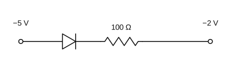
- KEAM 2024Set eng-2024-06084 marksMCQQ.In the circuit given below, the current is (A) 0.10 A (B) 10−3 A (C) 0.5 A (D) 1 A (E) 0A
›Reveal solutionSolution
With the p-side (anode) at −5 V and the n-side (cathode) at −2 V, the anode is more negative than the cathode, so the diode is reverse biased and passes essentially no current.
A junction diode conducts (forward bias) only when its anode (p-side) is at a higher potential than its cathode (n-side). In this circuit the p-side faces the −5 V terminal, so the anode potential is −5 V, and the cathode side connects through the resistor toward the −2 V terminal. Comparing potentials, t …
- KEAM 2023Set eng-2023-P1-A14 marksMCQQ.Each side of a regular hexagon has resistance R. The effective resistance between the two opposite vertices of the hexagon is: (A) R (B) 2R (C) 23R (D) 32R (E) 3R
›Reveal solutionSolution
The resistance between opposite vertices of the hexagon is 23R.
Concept and Intuition
A hexagon of six equal resistors between two opposite (diametrically opposite) vertices splits into two parallel paths, each consisting of three resistors in series.
Step-by-Step Solution
- Each path between opposite vertices has 3 sides: 3R.
- The two paths are in parallel: 3R+3R(3R)(3R)=6R9R2=23R. …
- KEAM 2023Set eng-2023-P1-A14 marksMCQQ.Find the effective resistance between points A and B. Each resistance is equal to R. [FIGURE] (A) 2R (B) 43R (C) 3R (D) 34R (E) 59R
›Reveal solutionSolution
Figure-dependent; the network of equal resistors reduces to 34R between A and B.
Step 1: Each element equals R; the effective resistance depends on the specific series/parallel topology shown in the (unavailable) figure. …
- KEAM 2022Set eng-2022-P1-A14 marksMCQQ.If the potential at A is greater than the potential at B, then the equivalent resistance of the circuit across AB is [FIGURE] (A) 4.4 Ω (B) 5.2 Ω (C) 6 Ω (D) 9 Ω (E) 3.6 Ω
›Reveal solutionSolution
Figure-dependent; the 'VA>VB' clause implies a polarity-sensitive (diode) branch, and the standard version of this network reduces to 3.6 Ω.
Step 1: The stem specifies a direction of higher potential (A over B), which is only meaningful when the circuit contains a diode (or similar one-way element) that either conducts or blocks depending on the sign of VA−VB.
Step 2: With VA>VB the conducting configuration selects a particular series/parallel combination of the resistors. …
🎓Unlock everything free for 14 days
- ✓Full step-by-step solutions
- ✓Concept-first explanations
- ✓Methods, shortcuts & mistakes
- ✓PYQ mapping + timed mock tests
Full access for 14 days. No credit card required.