Mathematics · Ch 1 — Mathematical Logic
Two switches in parallel
Two switches in parallel
Two Switches in Parallel
Now wire and side by side, each offering its own path to the lamp (a parallel connection), with for and for . Current reaches the lamp as long as at least one path is closed — the behaviour of disjunction .
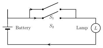
Drawn by us to help you understand the concept clearly, and verified to make sure it's accurate. For exams, practice from your textbook's own diagram.
What this figure shows. Figure 1.4 shows switches and as two separate side-by-side branches that both feed the same lamp , so current can reach the lamp through EITHER branch — both need not be closed. With for ' is on' and for ' is on', the lamp glows whenever or (or both) is true, failing only when both are off — the truth condition of the disjunction $p …
| 1 | 1 | 1 |
| 1 | 0 | 1 |
| 0 | 1 | 1 |
| 0 | 0 | 0 |
The lamp is dark only when both switches are off; a parallel connection is the circuit picture of OR.
With series = AND, parallel = OR, and a complementary switch = NOT now established, any circuit built from switches can be translated into a logical expression, and any logical expression can equally be built as a circuit — which is exactly what the worked examples below do.
Worked Example 1 — reading circuits into symbolic form. Three circuits (using switches , and in the third case , all controlling a lamp ) are to be written symbolically and given their input-output tables.
(i) With for and for , this circuit's expression is . Building the table column by column:
| 1 | 1 | 0 | 0 | 1 | 0 | 1 |
| 1 | 0 | 0 | 1 | 1 | 0 | 1 |
| 0 | 1 | 1 | 0 | 1 | 0 | 1 |
| 0 | 0 | 1 | 1 | 0 | 1 | 1 |
Every row gives 1 — the last column is all ones, so this circuit is a tautology: however the two switches are set, the lamp always glows.
(ii) With for , for , for , the expression is . Here is 1 exactly when and agree (both on or both off), and the whole expression additionally needs on:
| result | ||||||
|---|---|---|---|---|---|---|
| 1 | 1 | 1 | 1 | 0 | 1 | 1 |
| 1 | 1 | 0 | 1 | 0 | 1 | 0 |
| 1 | 0 | 1 | 0 | 0 | 0 | 0 |
| 1 | 0 | 0 | 0 | 0 | 0 | 0 |
| 0 | 1 | 1 | 0 | 0 | 0 | 0 |
| 0 | 1 | 0 | 0 | 0 | 0 | 0 |
| 0 | 0 | 1 | 0 | 1 | 1 | 1 |
| 0 | 0 | 0 | 0 | 1 | 1 | 0 |
The lamp glows only when and agree AND is on (rows 1 and 7).
(iii) With for , the expression is :
| result | ||||||
|---|---|---|---|---|---|---|
| 1 | 1 | 1 | 1 | 1 | 1 | 1 |
| 1 | 1 | 0 | 1 | 0 | 1 | 0 |
| 1 | 0 | 1 | 1 | 1 | 0 | 0 |
| 1 | 0 | 0 | 1 | 0 | 0 | 0 |
| 0 | 1 | 1 | 1 | 1 | 1 | 1 |
| 0 | 1 | 0 | 1 | 1 | 1 | 1 |
| 0 | 0 | 1 | 0 | 1 | 0 | 0 |
| 0 | 0 | 0 | 0 | 1 | 0 | 0 |
Notice always equals itself (an instance of the Absorption Law), so the lamp really only needs on together with on or off — the table confirms it lights only where and ( or ).
Worked Example 2 — building circuits from expressions. Given three logical expressions (with for ), each is translated into a switch network by reading as switches wired in series and as branches wired in parallel; no input-output table is needed here, only the circuit layout.
(i) — since disjunction only ever adds parallel branches, this circuit is four paths side by side between the two terminals: a lone switch ; a series pair ; a series pair ; and a lone switch .
(ii) — three parallel branches: all in series; a lone switch ; and in series.
(iii) — three parallel branches: in series; in series; and in series.
Worked Example 3 — simplifying to fewer switches. A circuit with switches and has expression — four switch-occurrences in all. The law chain below finds an equivalent circuit using as few switches as possible:
— Distributive Law, factoring out of the last two terms
— Complement Law,
— Identity Law,
— Commutative Law
— Distributive Law
— Complement Law,
— Identity Law,
So this four-switch circuit is logically identical to just two switches, and (the complements of and ), wired in parallel — the minimum arrangement for this expression.
Worked Example 4 — expressing, tabulating, and interpreting. With for and for , a given circuit's expression is :
| result | ||||||
|---|---|---|---|---|---|---|
| 1 | 1 | 0 | 0 | 1 | 0 | 0 |
| 1 | 0 | 0 | 1 | 1 | 0 | 0 |
| 0 | 1 | 1 | 0 | 1 | 1 | 0 |
| 0 | 0 | 1 | 1 | 0 | 0 | 0 |
Every row is 0. Algebraically this checks out too: , a contradiction. Interpretation: the lamp never glows, no matter how the two switches are set.
Worked Example 5 — simplifying to a constant. With for and for , a circuit's expression is :
— Associative Law
— Distributive Law
— Complement Law,
— Identity Law,
— Associative Law
— Complement Law,
— Identity Law,
Conclusion: the expression collapses to the contradiction , so the lamp will not glow regardless of how the switches are set.
Worked Example 6 — symbolic form, table, and simplification together. With for : …
| p (S1) | q (S2) | p ∨ q |
|---|---|---|
| 1 | 1 | 1 |
| 1 | 0 | 1 |