Mathematics · Ch 1 — Mathematical Logic
Two switches in series
Two switches in series
Applying Logic to Switching Circuits
The algebra of logical statements has a striking twin in electrical switching networks — an analogy first pointed out by Claude Shannon in 1930. Just as a statement is either true or false, a switch in a circuit is either on or off, so the same connectives (, , ) that describe statements can describe circuits too.
A switch is a two-state device that controls whether current can flow through a branch of a circuit; switches are labelled . When a switch is closed (on), current passes through it; when it is open (off), it blocks the current. A lamp wired through a switch glows exactly when is closed and stays dark when is open.
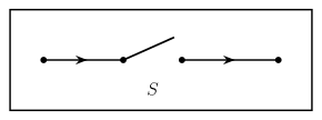
Drawn by us to help you understand the concept clearly, and verified to make sure it's accurate. For exams, practice from your textbook's own diagram.
What this figure shows. Figure 1.1 shows a single switch, denoted generically by (or when several appear in one circuit) — a two-state device that either allows or blocks current, exactly mirroring a statement's two possible truth values. Current flows left-to-right th …
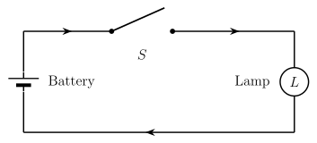
Drawn by us to help you understand the concept clearly, and verified to make sure it's accurate. For exams, practice from your textbook's own diagram.
What this figure shows. Figure 1.2 is the simplest complete circuit: one lamp wired in a loop with a battery through a single switch . Closing (turning it 'on') completes the circuit and the lamp glows; opening (turning it 'off') breaks the circuit and the lamp stays dark — the basic on/off ↔ true/false, glows ↔ s …
To connect this to logic, every switch in a circuit is matched to a statement letter. Two switches that are always in the same state (both open or both closed together) are called equivalent switches and share the same letter — for instance switch is written as . Two switches that are always in opposite states are complementary switches: if one switch is written , the other (its complement, ) is written . Note that the circuit diagram itself never shows which state a switch is actually in.
Because the real state of any switch is not fixed in advance, we list every possible combination of on/off values for all the switches involved and record the resulting lamp state for each combination — this record is called the Input-Output table (or switching table), the electrical counterpart of a truth table. By convention, stands for "on" (closed) and for "off" (open). …
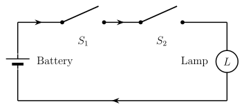
Drawn by us to help you understand the concept clearly, and verified to make sure it's accurate. For exams, practice from your textbook's own diagram.
What this figure shows. Figure 1.3 shows switches and wired one after another along the single path to the lamp , so current must pass through BOTH switches to reach the lamp. With for ' is on' and for ' is on', the lamp glows exactly when and are both true — the truth condition of the conjunction …
| p (S1) | q (S2) | p ∧ q |
|---|---|---|
| 1 | 1 | 1 |
| 1 | 0 | 0 |