Chemistry · Ch 2 — Electrochemistry
Secondary Batteries
Secondary Batteries
A secondary battery differs from a primary one in that it can be recharged: once discharged, passing a current back through the cell in the reverse direction restores the original reactants, so the battery can be used again. A good secondary cell can withstand a large number of such discharge-charge cycles over its lifetime.
The Lead Storage Battery
The lead storage battery is the most widely used secondary cell, familiar as the battery found in automobiles and inverters. It is built from a lead anode and a cathode consisting of a grid of lead packed with lead dioxide (). The electrolyte is a 38% solution of sulphuric acid.
While the battery is in use (discharging), the electrode reactions are:
Anode:
Cathode:
Adding the two half-reactions gives the overall cell reaction on discharge:
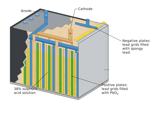
When the battery is charged, this whole process runs in reverse: the lead sulphate () that had deposited on both the anode and the cathode during discharge is converted back — to metallic lead at the anode and to lead dioxide at the cathode — regenerating the battery's original state (as shown alongside).
Drawn by us to help you understand the concept clearly, and verified to make sure it's accurate. For exams, practice from your textbook's own diagram.
The figure shows a cutaway view of a lead storage battery. The rectangular outer case has filler caps on top (for adding distilled water or acid) and two terminals: the anode (negative) and cathode (positive). Inside, alternating vertical plates are arranged:
- Negative plates: lead grids filled with spongy lead ().
- Positive plates: lead grids filled with lead dioxide ().
- Separators: thin insulating sheets between the plates to prevent short circuits.
- Electrolyte: all plates are immersed in 38% sulphuric acid ().
- Top bars: connect all like plates (all negative plates together, all positive plates together) to their respective terminal.
The physical idea is that during discharge, the battery converts chemical energy into electrical energy through spontaneous redox reactions. During charging, an external voltage reverses the reactions, restoring the original chemicals.
The key half-reactions during discharge are:
At the anode (negative plate):
At the cathode (positive plate):
The overall cell reaction during discharge is:
Here:
- is spongy lead (negative plate).
- is lead dioxide (positive plate).
- is sulphuric acid (electrolyte).
- is lead sulphate (solid product that coats both plates).
- is water (dilutes the acid).
During charging, the reactions are reversed: …
The Nickel-Cadmium Cell …
Drawn by us to help you understand the concept clearly, and verified to make sure it's accurate. For exams, practice from your textbook's own diagram.
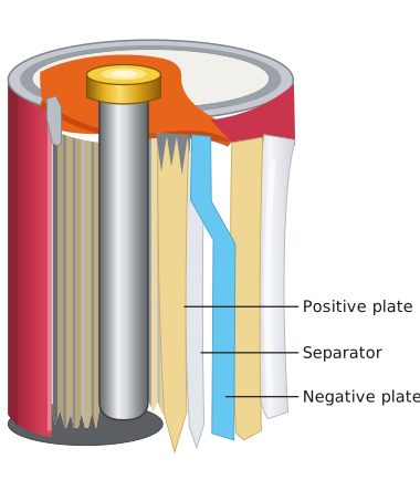
The figure shows a cutaway view of a cylindrical nickel-cadmium (Ni-Cd) cell. The key structural feature is the jelly-roll arrangement: three flexible layers are rolled together tightly around a central rod and placed inside the metal casing.
- Central rod: Acts as the core around which the layers are wound.
- Positive plate: One of the rolled layers, made of nickel hydroxide () during discharge.
- Negative plate: Another rolled layer, made of cadmium ().
- Separator layer: A porous material soaked in moist sodium hydroxide () or potassium hydroxide (). This layer physically separates the positive and negative plates while allowing ion flow through the alkaline electrolyte.
The physical idea the figure teaches is that a secondary (rechargeable) battery can be made compact and durable by rolling the electrodes and separator into a tight spiral. This design maximizes the surface area of the electrodes in a small volume, improving the cell's capacity and lifespan compared to flat-plate designs like the lead storage cell.
The textbook uses this figure to introduce the overall discharge reaction of the Ni-Cd cell:
- : Solid cadmium (negative electrode material).
- : Solid nickel(III) hydroxide (positive electrode material).
- : Solid cadmium oxide (product at negative electrode).
- : Solid nickel(II) hydroxide (product at positive electrode).
- : Liquid water (byproduct). …