Physics · Ch 3 — Current Electricity
Cells in Series and in Parallel
Cells in Series and in Parallel
Why Combine Cells?
Just as resistors can be connected in series or parallel to get a desired equivalent resistance, cells (batteries) can also be combined. The goal is to replace a network of cells with a single equivalent cell having an equivalent emf and an equivalent internal resistance . This makes circuit analysis simpler.
Cells in Series
Setup: Two cells are connected in series when the negative terminal of one is joined to the positive terminal of the other. The free terminals are A and C.
Let:
- = emf of each cell
- = internal resistance of each cell
- = current flowing through the combination (leaving each cell from its positive terminal)
Derivation of and :
- Potential difference across the first cell (between A and B):
- Potential difference across the second cell (between B and C):
- Total potential difference across the combination (between A and C):
- For an equivalent single cell between A and C, we would have:
- Comparing the two expressions for gives the rules for series combination:
Important Note on Polarity:
If the cells are connected with opposite polarity (e.g., negative of first to negative of second), the emf of the reversed cell enters with a negative sign. For :
General Rule for cells in series:
- The equivalent emf is the algebraic sum of the individual emfs (positive if current leaves from the positive terminal, negative otherwise).
- The equivalent internal resistance is the arithmetic sum of the individual internal resistances.
Cells in Parallel
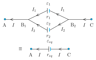
Setup: Two cells are connected in parallel when their positive terminals are joined together (at ) and their negative terminals are joined together (at ).
Let:
- = currents leaving the positive electrodes of the first and second cell, respectively.
- = total current flowing out of the combination from .
Derivation of and :
- Current conservation at junction :
- Potential difference across the terminals of the first cell (between and ):
- Potential difference across the terminals of the second cell (between and ):
- Express and in terms of :
- Substitute into the current equation:
- Solve for :
- For an equivalent single cell between and , we would have:
- Comparing the two expressions for gives the rules for parallel combination:
$$\boxed{\frac{\varepsilon_{eq}}{r_{eq}} = \frac{\varepsilon_1}{r_1} + \frac{\varepsilon_2}{r_2}}$$ …

Drawn by us to help you understand the concept clearly, and verified to make sure it's accurate. For exams, practice from your NCERT textbook's own diagram.
The figure shows two equivalent circuit diagrams separated by an equivalence sign (). On the left is a series combination of two cells, and on the right is a single equivalent cell that replaces the combination when considering the terminals A and C.
Left diagram: A horizontal wire has three labelled nodes: A (left), B (middle), and C (right). Between A and B is a battery symbol (long plate = positive, short plate = negative) labelled with emf , and below it a resistor representing its internal resistance. Between B and C is a second battery with emf and internal resistance . The positive terminal of the first cell is connected to the negative terminal of the second cell — this is series-aiding connection. A current flows leftward along the top wire (arrow pointing from C toward A), meaning the conventional current direction is from C to A through the external circuit.
Right diagram: A single wire from A to C contains one battery symbol with emf and one resistor , with the same current flowing leftward. This represents the equivalent cell that behaves identically to the series combination when connected across points A and C.
Physical idea: When cells are connected in series, the total potential difference across the combination is the sum of the individual terminal voltages, and the total internal resistance is the sum of the individual internal resistances. The figure teaches that a series combination can be replaced by a single cell without changing the external circuit behaviour.
Key formulas derived from this figure:
The potential difference between A and C for the left circuit is:
For the equivalent cell on the right:
Comparing gives:
Here:
- are the emfs of the individual cells (in volts),
- are their internal resistances (in ohms), …
Drawn by us to help you understand the concept clearly, and verified to make sure it's accurate. For exams, practice from your NCERT textbook's own diagram.
The figure shows two cells connected in parallel-aiding — both positive terminals joined at node and both negative terminals joined at node . The external circuit connects across points (left) and (right), with the total current entering at and leaving at .
Left side of the diagram:
- Node connects to .
- From , two parallel branches run to :
- Upper branch: cell of emf with internal resistance , carrying current .
- Lower branch: cell of emf with internal resistance , carrying current .
- connects to node .
- The external current flows from to (leftward arrowheads indicate direction).
Right side of the diagram (after the symbol):
- A single equivalent cell of emf and internal resistance placed between and , carrying the same total current .
Physical idea:
When cells are in parallel, the total current splits into and through each branch. The potential difference across the combination (between and ) is the same for both cells. By applying Kirchhoff’s laws, the combination behaves like a single cell whose emf and internal resistance are given by the parallel combination formulas.
Key formulas derived from this figure:
The equivalent internal resistance:
The equivalent emf:
An alternative form using :
Symbol meanings:
- : emf of each cell (in volts)
- : internal resistance of each cell (in ohms)
- : currents through each branch (in amperes)
- : total current supplied to the external circuit …