Q.Explain with the help of circuit diagram, how V–I characteristics of pn junction diode are obtained in forward biasing.
You're viewing a preview — the full solution, concept, methods & PYQ mapping are locked.
Start your 14-day free trial to unlock the full solution →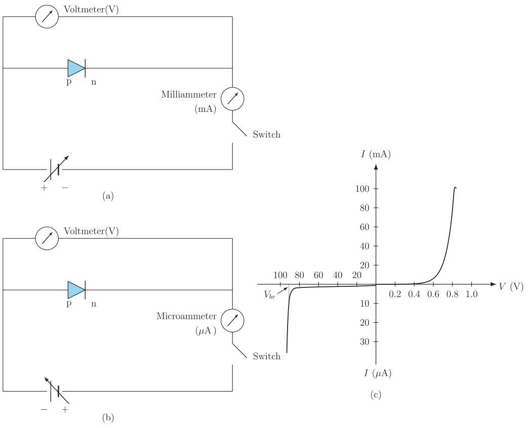
A simple series circuit with a variable forward-bias voltage source, ammeter, and voltmeter across a pn junction diode lets you trace the forward characteristic curve, showing a threshold (knee) voltage followed by a steep current rise.
Circuit for forward bias V-I characteristics:
The p-side of the diode is connected to the positive terminal of a battery (through a rheostat/potentiometer for varying voltage), and the n-side to the negative terminal — this is forward biasing. A milliammeter (mA) is connected in series with the diode to measure current, and a voltmeter is connected in parallel across the diode to measure the voltage across it.
Procedure:
- Using the rheostat, the forward voltage across the diode is increased in small steps starting from 0 V.
- At each step, the voltmeter reading (V) and the corresponding milliammeter reading (I) are recorded.
- A graph of forward current (I) on the y-axis vs forward voltage (V) on the x-axis is plotted.
Nature of the graph:
- For small forward voltages, the current is almost negligible, because the applied voltage isn't yet strong enough to overcome the potential barrier at the junction. …
Unlock everything free for 14 days
- Full step-by-step solutions
- Concept-first explanations
- Methods, shortcuts & mistakes
- PYQ mapping + timed mock tests
Full access for 14 days. No credit card required.