Question 50 of 50
Q.(a) Draw graphs showing the variations of inductive reactance and capacitive reactance with frequency of the applied ac source.
(b) Draw the phasor diagram for a series RC circuit connected to an ac source.
(c) An alternating voltage of 220 V is applied across a device X, a current of 0.25 A flows, which lag behind the applied voltage in phase by radian. If the same voltage is applied across another device Y, the same current flows but now it is in phase with the applied voltage.
(i) Name the devices X and Y.
(ii) Calculate the current flowing in the circuit when the same voltage is applied across the series combination of X and Y.
OR
(a) State the principle of working of a transformer.
(b) Define efficiency of a transformer.
(c) State any two factors that reduce the efficiency of a transformer.
(d) Calculate the current drawn by the primary of a 90% efficient transformer which steps down 220 V to 22 V, if the output resistance is 440 .
Rajasthan RbseCBSE Class XII Board 2018Subjective· 5mImportance★★★★★
100% · 50/50 Questions
You're viewing a preview — the full solution, concept, methods & PYQ mapping are locked.
Start your 14-day free trial to unlock the full solution →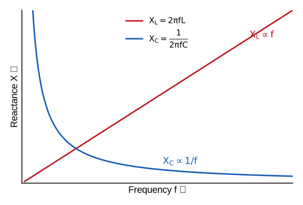
(line), (hyperbola); X is a pure inductor, Y a pure resistor; series current A. (OR transformer: mA.)
- Reactance vs frequency. Inductive reactance — a straight line through the origin, slope . Capacitive reactance — a rectangular hyperbola falling with .
- Series RC phasor. Take current as reference. is in phase with (along it); lags by (drawn downward). The resultant applied voltage lags... in fact the current leads the applied voltage by .
- Identify devices and find current.
- X: current lags voltage by pure inductor. Its reactance
- Y: current in phase with voltage pure resistor,
- In series: …
Unlock everything free for 14 days
- Full step-by-step solutions
- Concept-first explanations
- Methods, shortcuts & mistakes
- PYQ mapping + timed mock tests
Full access for 14 days. No credit card required.