Physics · Ch 3 — Current Electricity
Cells, EMF, Internal Resistance
Cells, EMF, Internal Resistance
What is a Cell?
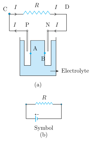
A cell is a device that maintains a steady current in a circuit by converting chemical energy into electrical energy. It has two electrodes — positive (P) and negative (N) — immersed in an electrolytic solution. The electrodes exchange charges with the electrolyte, creating potential differences at the electrode-electrolyte interfaces.
Electromotive Force (emf)
When no current flows through the cell (open circuit), the electrolyte has the same potential everywhere. The potential difference between the positive and negative electrodes is:
- is the potential of the positive electrode relative to the adjacent electrolyte.
- is the magnitude of the negative potential of the negative electrode relative to the adjacent electrolyte.
- is called the electromotive force (emf) of the cell.
Important: emf is a potential difference, not a force. The name is historical.
Internal Resistance
When a resistor is connected across the cell, a current flows. Inside the cell, the same current flows through the electrolyte from the negative to the positive electrode. The electrolyte has a finite resistance called the internal resistance, denoted by .
Potential Difference When Current Flows
When current flows through the cell, the potential difference between the terminals P and N is less than the emf because of the voltage drop across the internal resistance:
- is the terminal voltage (potential difference across the external circuit).
- is the emf.
- is the current.
- is the internal resistance.
The negative sign arises because current flows from B to A inside the electrolyte, opposite to the direction of the emf.
Relation Between Terminal Voltage, emf, and External Resistance
From Ohm's law, the terminal voltage across the external resistor is also:
Equating the two expressions for :
Rearranging gives the total circuit current:
…
Drawn by us to help you understand the concept clearly, and verified to make sure it's accurate. For exams, practice from your textbook's own diagram.
The figure has two panels, (a) and (b), which together illustrate the physical structure of an electrolytic cell and its circuit symbol.
Panel (a) shows a beaker containing a shaded electrolyte (the conducting liquid). Two vertical electrodes are immersed in it: the left electrode is labelled P (positive terminal) and the right electrode is labelled N (negative terminal). Inside the electrolyte, two points are marked: A near electrode P, and B near electrode N. These points represent the electrolyte immediately adjacent to each electrode. Above the beaker, an external circuit connects a node C (top-left) through a resistor R (drawn as a zig-zag) to a node D (top-right). Arrowheads labelled I show the direction of current flow around the loop: through the external resistor from P to N (C → R → D), and through the electrolyte from N to P (the internal path). This panel demonstrates that the same current flows both inside and outside the cell.
Panel (b) shows the standard symbol for a cell: a long thin plate (the positive terminal, +) and a short thick plate (the negative terminal, –). A resistor is drawn across the top, connected by wires to the battery symbol. This symbol is used in circuit diagrams to represent the cell, with the + side corresponding to electrode P and the – side to electrode N.
Physical idea: The cell converts chemical energy into electrical energy. When no current flows (open circuit), the potential difference between P and N is the electromotive force (emf) . When current flows, the electrolyte itself has a finite internal resistance , which causes a voltage drop inside the cell.
Key formulas developed from this figure:
- The emf is the sum of the potential differences at the two electrode–electrolyte interfaces:
where is the positive potential of P relative to point A, and is the magnitude of the negative potential of N relative to point B.
- When a current flows through the cell, the terminal voltage (the potential difference between P and N) is: …