Physics · Ch 4 — Moving Charges and Magnetism
Introduction
Introduction
The Discovery That Linked Electricity and Magnetism
For over 2000 years, electricity and magnetism were studied as separate phenomena. This changed in 1820, when Danish physicist Hans Christian Oersted showed they were intimately connected.
Oersted's Experiment: During a lecture demonstration, Oersted placed a current-carrying wire near a magnetic compass needle and noticed the needle deflected — a clear sign that an electric current produces a magnetic field.
Key Observations from Oersted's Experiment
- Direction of deflection: The compass needle aligns tangentially to an imaginary circle centred on the wire, with the plane of the circle perpendicular to the wire.
- Effect of reversing current: Reversing the current's direction reverses the needle's orientation.
- Effect of current magnitude and distance: The deflection grows larger as the current increases or as the needle is brought closer to the wire.
- Visual evidence: Iron filings sprinkled around the wire arrange themselves in concentric circles centred on the wire, confirming the circular shape of the field.
The Core Conclusion
Oersted concluded that moving charges (currents) produce a magnetic field in the surrounding space.
From Oersted to Maxwell
Intense experimentation followed Oersted's discovery. By 1864, James Clerk Maxwell had unified the laws of electricity and magnetism into a single theory, which led to the realisation that light itself is an electromagnetic wave. Hertz later demonstrated radio waves, and J. C. Bose and Marconi advanced their production — discoveries that, together with 20th-century advances in generating, amplifying, transmitting, and detecting electromagnetic waves, transformed technology.
What This Chapter Covers
This chapter examines how a magnetic field exerts forces on moving charged particles — electrons, protons, and current-carrying wires — and how currents themselves produce magnetic fields. It also introduces the cyclotron, a device that accelerates charged particles to very high energies, and the galvanometer, an instrument used to detect currents and voltages.
Notation Convention for Diagrams
Throughout this chapter (and the next), a dot () represents a current or field coming out of the page, toward the reader, while a cross () represents a current or field going into the page, away from the reader.
Drawn by us to help you understand the concept clearly, and verified to make sure it's accurate. For exams, practice from your textbook's own diagram.
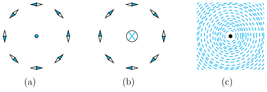
Fig. 4.1 is a three‑panel illustration that establishes the fundamental geometry of the magnetic field around a long, straight current‑carrying wire. The wire is perpendicular to the plane of the paper, so it appears as either a dot or a cross at the centre of each panel.
Panel (a) shows a central dot (), which represents current coming out of the page (toward the reader). Around this dot, eight compass needles are arranged in a ring. Each needle is tangent to an imaginary circle centred on the wire, and the darkened (north) tips point anticlockwise when viewed from above. This demonstrates that the magnetic field lines form concentric circles around the wire, with a definite sense of direction.
Panel (b) shows a central cross (), representing current going into the page (away from the reader). The same ring of compass needles now has its north tips pointing clockwise. Reversing the current direction reverses the magnetic field direction.
Panel (c) shows a central dot () surrounded by dense short dashes that form concentric circles — these are iron filings that align themselves along the magnetic field lines, confirming the circular pattern.
Physical idea: A steady electric current produces a magnetic field that circulates around the wire. The field lines are closed circles centred on the wire, lying in planes perpendicular to it. The direction of the field is given by the right‑hand rule: if the thumb points along the current (out of the page for , into the page for ), the curled fingers show the direction of the magnetic field (anticlockwise for , clockwise for ).
Key formula developed from this geometry is the magnetic field due to a long straight wire:
where:
- is the magnitude of the magnetic field at a point (in tesla, T),
- is the permeability of free space,
- is the current in the wire (in amperes, A),
- is the perpendicular distance from the wire to the point (in metres, m).
The field is tangential to the circle of radius , and its direction is given by the right‑hand rule. The formula shows that is inversely proportional to — the field weakens as you move away from the wire — and directly proportional to .