Chemistry · Ch 8 — Organic Chemistry – Some Basic Principles and Techniques
Three-Dimensional Representation of Organic Molecules
Three-Dimensional Representation of Organic Molecules
Representing Three-Dimensional Structures on Paper
Organic molecules are three-dimensional objects, but we usually work with them on a flat page or screen. To bridge that gap, chemists have developed a simple visual language that lets a two-dimensional drawing convey depth. The key is the wedge formula, which uses three kinds of lines to show the direction a bond points in space.
The plane of the paper is the reference surface. Any bond that lies exactly in this plane is drawn as a normal straight line (). Bonds that come out of the plane — toward you, the observer — are drawn as a solid wedge. Bonds that go behind the plane — away from you — are drawn as a dashed wedge.
A quick way to remember the wedge convention: the solid wedge looks like a triangle getting wider as it comes toward you — think of it as the bond "popping out" of the page. The dashed wedge looks like a set of dashes receding into the distance — the bond is "sinking away" from you.
The wedge is always drawn with its broad end toward the observer. That means the wide part of the solid wedge is closest to you, and the wide part of the dashed wedge is also drawn as if you are looking at it from the front — but the bond itself goes away from you.
The Three Bond Types in a Wedge Formula
Every bond in a wedge drawing falls into one of three categories:
| Line type | What it represents |
|---|---|
| Normal line () | Bond lying in the plane of the paper |
| Solid wedge () | Bond projecting out of the plane, toward the observer |
| Dashed wedge | Bond projecting behind the plane, away from the observer |
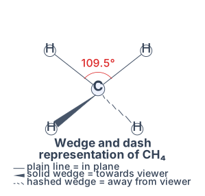
Drawn by us to help you understand the concept clearly, and verified to make sure it's accurate. For exams, practice from your NCERT textbook's own diagram.
The wedge-and-dash diagram of methane is your first real look at three-dimensional structure on a flat page. The central carbon sits at the intersection of four bonds, but they are not drawn identically. Two bonds lie in the plane of the paper — these are ordinary straight lines. One bond comes out of the page toward you: a solid wedge, wider at the end where the hydrogen sits. The fourth bond recedes behind the page: a dashed wedge (or a set of parallel dashes) that narrows toward the carbon.
The angle marked between any two adjacent bonds is , the tetrahedral angle. That number is not arbitrary — it is the angle that maximises the distance between four electron pairs around a central atom, minimising repulsion. The figure shows that all four C–H bonds are equivalent in length and in angle, even though the drawing forces some to appear shorter or longer because of perspective.
The solid wedge does not mean the bond is stronger or longer — it only means the hydrogen is closer to you than the carbon is. The dashed wedge means the hydrogen is farther away. The plain lines are bonds that lie exactly in the plane of the page.
The physical idea the figure teaches is that a molecule is not flat. A student who sees only a structural formula like might imagine a cross shape with angles. The wedge-and-dash drawing corrects that: the hydrogens are arranged at the corners of a regular tetrahedron, with the carbon at its centre. No two bonds are apart; every bond angle is .
The textbook uses this figure to introduce the tetrahedral geometry and the valence shell electron pair repulsion (VSEPR) theory that predicts it. The key formula is not a calculation but a geometric relationship: for a perfect tetrahedron, the bond angle satisfies
which gives , rounded to in most textbooks. Here is the angle between any two bonds from the central carbon to two different hydrogens. The derivation comes from placing the four hydrogens at the vertices of a regular tetrahedron and the carbon at its centre; the dot product of two position vectors yields . …
Figure 8.1 shows methane drawn this way: two of the four C–H bonds lie in the plane of the paper, one solid wedge points toward you, and one dashed wedge points behind the page — together they convey methane's tetrahedral shape on a flat surface.
Molecular Models
Beyond drawings on paper, chemists use molecular models — physical devices of wood, plastic or metal (and, today, computer graphics) — to visualise and perceive the three-dimensional shapes of organic molecules. Three kinds are commonly used, each with its own emphasis:
- Framework model — shows only the bonds connecting the atoms, not the atoms themselves. It emphasises the pattern of bonds in the molecule while ignoring the sizes of the atoms. …
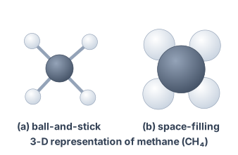
Drawn by us to help you understand the concept clearly, and verified to make sure it's accurate. For exams, practice from your NCERT textbook's own diagram.
Figure 8.2 in your NCERT textbook shows two different ways to draw the same molecule — methane, CH₄. The figure has two panels side by side, labelled (a) and (b). Neither panel has axes or curves; this is a structural diagram, not a graph.
Panel (a) is a ball-and-stick model. A larger sphere represents the carbon atom at the centre. Four smaller spheres, each representing a hydrogen atom, are attached to the carbon by thin sticks. The sticks are not all in the same plane — they splay outward in a three-dimensional arrangement. The key visual point is that the four hydrogen atoms are not at 90° to each other; they point toward the four corners of a regular tetrahedron. The sticks make the geometry explicit: you can see the bond directions and the angles between them.
Panel (b) is a space-filling model. Here, the atoms are drawn as fused spheres that touch each other at their van der Waals radii. There are no sticks. The carbon sphere is larger than the hydrogen spheres, and they overlap slightly where bonds form. This model hides the bond angles but shows the actual space the molecule occupies — its "size" and shape as felt by other molecules.
The two models teach complementary ideas. The ball-and-stick model shows geometry (bond angles, arrangement in space). The space-filling model shows size (relative atomic volumes, molecular surface). Both are needed to understand a molecule fully.
The physical idea the figure teaches is that a molecule is not flat. Even a simple molecule like methane has a definite three-dimensional shape. The carbon atom sits at the centre of a tetrahedron, and the four hydrogen atoms occupy the four vertices. The angle between any two C–H bonds is the tetrahedral angle, .
The textbook develops the tetrahedral geometry of carbon with this figure. The central formula is the relationship between the tetrahedral bond angle and the geometry of a regular tetrahedron. If you place the carbon at the centre of a cube and the four hydrogens at alternate corners, the bond angle satisfies:
This gives . Here, is the angle between any two C–H bonds. The value comes from the dot product of vectors from the centre of a cube to two non-adjacent vertices.
You do not need to derive for the exam, but you must know that the tetrahedral angle is and that it arises because carbon uses hybrid orbitals.
The figure also sets up the idea of three-dimensional representation on paper. In later sections, you will learn to use wedges (thick lines for bonds coming toward you) and dashed lines (for bonds going away) to show 3D structure in 2D drawings. The ball-and-stick model in Fig. 8.2 is the conceptual foundation for those conventions. …