Physics · Ch 4 — Laws of Motion
Solving Problems in Mechanics
Solving Problems in Mechanics
Solving Problems in Mechanics
The three laws of motion form the complete foundation of mechanics. With them, you can handle a vast range of problems — but a typical problem rarely involves a single isolated body under known forces. More often, you face an assembly of bodies that exert forces on each other, with each body also experiencing gravity.
The key insight is this: you can choose any part of the assembly, call it your system, and apply the laws of motion to that part alone — provided you include every force on the system due to the remaining parts (the environment). This is exactly what we have done in all the solved examples so far.
The Systematic Problem-Solving Procedure
To handle any mechanics problem methodically, follow these five steps:
-
Draw a schematic diagram showing all parts of the assembly — the bodies, links, supports, strings, pulleys, and so on.
-
Choose a convenient part of the assembly as your system. This choice is yours; pick whatever makes the analysis simplest.
-
Draw a separate diagram showing only this system and all forces on it from the environment. This includes forces from the remaining parts of the assembly and from any other agencies (gravity, friction, etc.). Do not include forces that the system exerts on the environment. This diagram is called a free-body diagram.
The term "free-body diagram" does not mean the system is free of net force. It simply means the body is isolated in the diagram, with all external forces drawn on it.
-
In the free-body diagram, label all forces you are sure of — their magnitudes and directions. For example, the direction of tension in a string is always along the string. Treat everything else as unknowns to be determined using the laws of motion.
-
If needed, repeat for another choice of system. When you do, use Newton's third law: if in the free-body diagram of body A the force on A due to B is shown as , then in the free-body diagram of B, the force on B due to A must be shown as .
Worked Example: Block and Cylinder on a Yielding Floor
Let us see this procedure in action with a complete example.
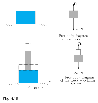
The situation: A wooden block of mass rests on a soft horizontal floor. An iron cylinder of mass is placed on top of the block. The floor yields steadily, and the block and cylinder together go down with an acceleration of . Take .
We need the action of the block on the floor (a) before the floor yields and (b) after the floor yields. We also need to identify all action-reaction pairs.
Part (a): Before the floor yields
The block is at rest on the floor. Choose the block as the system.
Free-body diagram of the block: Two forces act on it:
- Gravitational force by the earth: , vertically downward.
- Normal force by the floor on the block, vertically upward.
Since the block is at rest, the net force on it must be zero (Newton's first law). Therefore:
By Newton's third law, the action of the block on the floor (the force exerted by the block on the floor) is equal in magnitude and opposite in direction to the force the floor exerts on the block. So the action is , vertically downward.
Part (b): After the floor yields
Now the block and cylinder move together downward with acceleration . Choose the system as the block plus the cylinder together.
Free-body diagram of the system: Two external forces act on it:
- Total gravitational force by the earth: , vertically downward.
- Normal force by the floor on the system, vertically upward.
The free-body diagram of the system does not show the internal forces between the block and the cylinder. Those forces cancel each other within the system and do not affect its motion as a whole.
Apply Newton's second law to the system. Take downward as positive:
By Newton's third law, the action of the system on the floor is , vertically downward.
Identifying Action-Reaction Pairs
For part (a):
- The force of gravity () on the block by the earth (call this action) and the force of gravity on the earth by the block (reaction), equal to directed upward (not shown in the figure).
- The force on the floor by the block (action) and the force on the block by the floor (reaction).
For part (b):
- The force of gravity () on the system by the earth (action) and the force of gravity on the earth by the system (reaction), equal to directed upward.
- The force on the floor by the system (action) and the force on the system by the floor (reaction).
- Additionally, the force on the block by the cylinder and the force on the cylinder by the block form an action-reaction pair. …
Drawn by us to help you understand the concept clearly, and verified to make sure it's accurate. For exams, practice from your NCERT textbook's own diagram.
The figure shows two separate free-body diagrams side by side, each representing a different stage of the same experiment. On the left is a wooden block alone, sitting at rest on a table. The only forces acting on it are its weight, downward, and the normal reaction from the table pushing upward. Because the block is stationary, Newton’s first law tells us these two forces must be equal in magnitude: .
On the right, an iron cylinder has been placed on top of the block. The combined weight of the block plus cylinder is now downward. The system is no longer at rest — it is accelerating downward at . The free-body diagram for the combined system shows the same two forces: the total weight down, and the normal reaction from the table up. But because the system is accelerating downward, the net force is not zero. Newton’s second law gives:
where the negative sign indicates downward acceleration. The total mass is . Solving, you get , which is less than .
The key physical idea is that when a system accelerates downward, the normal reaction from the supporting surface is less than the weight. This is why you feel lighter in a descending elevator. The figure contrasts the static case () with the accelerating case (), using the same two-force setup.
The textbook uses this figure to develop the general principle: for any object on a horizontal surface, if the surface itself accelerates (or if the object is part of a larger accelerating system), the normal force adjusts to satisfy . The formula that emerges is:
where is the normal reaction, is the mass, is the acceleration due to gravity, and is the downward acceleration of the system. If , this reduces to .
The figure also teaches a crucial problem-solving habit: always draw separate free-body diagrams for different situations. The left panel shows equilibrium; the right panel shows non-equilibrium. Comparing them side by side makes it obvious that the normal force is not a fixed value — it depends on the motion of the system. …