Q.Let there be n resistors R1…Rn with Rmax=max(R1…Rn) and Rmin=min{R1…Rn}. Show that when they are connected in parallel, the resultant resistance RP<Rmin and when they are connected in series, the resultant resistance RS>Rmax. Interpret the result physically.
🔒You're viewing a preview — the full solution, concept, methods & PYQ mapping are locked.
🔒 Start your 14-day free trial to unlock the full solution →Concept understanding — Wheatstone Bridge Symmetry
Wheatstone Bridge Symmetry
Four resistors are arranged in a diamond. A battery sits across the top and bottom points; a sensitive galvanometer bridges the left and right points. The question is: when does no current flow through the galvanometer? The answer is symmetry.
The Intuition
Treat the bridge as two parallel voltage dividers — two resistors in series on the left, two in series on the right — with the galvanometer joining their midpoints. If both dividers produce the same midpoint voltage, there is no potential difference across the galvanometer and no current flows: the bridge is balanced. This happens when the resistance ratio on the left arm equals the ratio on the right arm.
Symmetry here means equal ratios, not equal resistances. 1 Ω with 2 Ω on one side balances 100 Ω with 200 Ω on the other.
The Precise Statement
Label the four resistors: R1 top-left, R2 bottom-left, R3 top-right, R4 bottom-right. The battery connects the top junction (between R1, R3) to the bottom junction (between R2, R4); the galvanometer connects the two midpoints. The bridge is balanced when
R2R1=R4R3
The balance condition is independent of the battery voltage and of the galvanometer's resistance — it depends only on the four resistor values.
Why This Matters
- Unknown resistance: put the unknown in place of R4, adjust the others until balanced, then R4=R3R1R2.
- Strain gauges: stretching slightly changes a resistance, unbalancing the bridge; the deflection measures the strain.
- Temperature sensors: a temperature-dependent resistor unbalances the bridge in proportion to the change. …
Why this formula?
Wheatstone Bridge Symmetry — Why the Formula Holds
The Wheatstone bridge is a circuit used to measure an unknown resistance by balancing two legs of a bridge. The key result is:
When the bridge is balanced, no current flows through the galvanometer, and:
R2R1=R4R3
Let's understand why this is true — not just memorize it.
1. The Circuit Setup
A Wheatstone bridge has four resistors arranged in a diamond:
- R1 and R2 in series on the left branch
- R3 and R4 in series on the right branch
- A galvanometer (sensitive current detector) connects the midpoints of the two branches
- A battery connects across the top and bottom
        A
       / \
      /   \
     R1    R3
     |     |
     G-----|   (G = galvanometer)
     |     |
     R2    R4
      \   /
       \ /
        B
2. The Condition for Balance — "No Current Through G"
Balance means the galvanometer shows zero deflection — no current flows through it. This implies points C (between R1 and R2) and D (between R3 and R4) are at the same electric potential. If VC=VD, no potential difference exists across the galvanometer, so no current flows.
3. Deriving the Ratio — Step by Step
Step 1: Branch currents
With no current through G, the left branch carries a single current I1 and the right branch a single current I2.
Step 2: Equal potentials at the midpoints
From A (common top) to the midpoints, since VC=VD:
I1R1=I2R3(1)
From the midpoints to B (common bottom), since VC=VD:
I1R2=I2R4(2)
Step 3: Divide (1) by (2)
I1R2I1R1=I2R4I2R3
The currents I1 and I2 cancel: …
Concept: Bounds on series and parallel combinations.
Parallel. For n resistors,
RP1=R11+R21+⋯+Rn1.
Every term is positive, and one of them is Rmin1 (the largest single reciprocal). Since the sum includes Rmin1 plus other positive terms,
RP1>Rmin1⇒RP<Rmin.
Series. RS=R1+R2+⋯+Rn. This sum contains Rmax plus other positive terms, so
RS>Rmax. …
Because a parallel combination sums reciprocals, its reciprocal exceeds the largest single reciprocal 1/Rmin, giving RP<Rmin; because a series combination sums resistances, its total exceeds the largest single term, giving RS>Rmax.
Parallel: RP<Rmin
For n resistors in parallel,
RP1=∑i=1nRi1=R11+R21+⋯+Rn1.
Among the reciprocals, the smallest resistance Rmin gives the largest reciprocal Rmin1. The right-hand side contains this term plus the other reciprocals, all of which are positive. Hence the whole sum is strictly greater than Rmin1 alone:
RP1=Rmin1+>0Ri=Rmin∑Ri1>Rmin1.
Since both sides are positive, taking reciprocals reverses the inequality:
RP<Rmin.
Do not write Ri1>Rmin1 — that is false, because Rmin gives the largest reciprocal. The correct argument keeps the Rmin1 term and adds the other positive terms to it. (Check: 1 Ω∥1000 Ω gives RP≈0.999 Ω<1 Ω=Rmin, not <Rmin/n.)
Series: RS>Rmax
For n resistors in series,
RS=∑i=1nRi=R1+R2+⋯+Rn.
This sum contains Rmax together with the remaining resistances, each positive:
RS=Rmax+>0Ri=Rmax∑Ri>Rmax.
Physical interpretation …
Method: Proving Bounds on Series and Parallel Resistance Combinations
Use this whenever you must prove an inequality about a combined resistance — for example, that a parallel combination is always smaller than its smallest member, or a series combination always larger than its largest — rather than compute an exact value.
Steps
Step 1: Write the exact combination formula
Parallel: RP1=∑i=1nRi1,Series: RS=∑i=1nRi
Step 2: Isolate the extremal term you're comparing against
Split the sum into "the term for the extreme value" plus "everything else":
RP1=Rmin1+∑Ri=RminRi1,RS=Rmax+∑Ri=RmaxRi
Step 3: Argue positivity of the remaining terms
Every resistance is positive, so every term split off in Step 2 is strictly positive. Adding a positive quantity to the extremal term makes the sum strictly greater than that extremal term alone — this single observation drives both halves of the proof.
Step 4: Convert back to the original quantity, watching the inequality's direction …
Showing the 12 most recent of 17 on this concept.
- TG EAPCET 2026Set eng-2026-05-10-FN1 markMCQQ.When two resistors are connected in the two gaps of a meter bridge, the balancing point is obtained at 25 cm from the left end of the bridge wire. When a 48 Ω resistor is connected in series to the smaller of the two resistors, the balancing point is obtained at 75 cm from the left end of the bridge wire. Then the initial values of the resistors connected in the left and right gaps of the bridge are respectively (A) 18 Ω, 54 Ω (B) 6 Ω, 18 Ω (C) 12 Ω, 36 Ω (D) 24 Ω, 72 Ω
›Reveal solutionSolution
This problem involves applying the meter bridge principle twice. We use the balancing point information to set up two equations relating the unknown resistances and then solve them simultaneously. The initial values of the resistors are 6 Ω and 18 Ω.
Concept and Intuition
The meter bridge is a practical application of the Wheatstone bridge, designed to measure an unknown electrical resistance. It consists of a uniform wire of 1-meter length (100 cm) stretched along a scale, and two gaps where resistors can be connected. A galvanometer is connected between a central terminal and a sliding jockey that can touch any point on the bridge wire.
The fundamental principle is to find a "balancing point" on the wire where the galvanometer shows zero deflection. When the galvanometer reads zero, it means no current flows through it, indicating that the potential difference across its terminals is zero. This condition signifies that the Wheatstone bridge is balanced.
At the balancing point, the ratio of the resistances in the two gaps is equal to the ratio of the lengths of the wire segments on either side of the balancing point. This is because the resistance of a uniform wire is directly proportional to its length.
For a balanced meter bridge, if RL is the resistance in the left gap, RR is the resistance in the right gap, and l is the balancing length from the left end of the bridge wire, then:
RRRL=100−ll
Step-by-step solution
- Analyze the first scenario: Let the initial resistance in the left gap be RL and in the right gap be RR. The problem states that the balancing point is obtained at l1=25 cm from the left end. Using the meter bridge formula:
RRRL=100−l1l1
Substitute the given balancing length:RRRL=100−2525
RRRL=7525
RRRL=31
This gives us our first relationship between $R_L$ and $R_R$:RR=3RL(Equation 1)
-
Identify the smaller resistor:
From Equation 1, since RR=3RL, it is clear that RL is the smaller of the two initial resistors. This identification is crucial because the next step involves connecting an additional resistor to the smaller one.
-
Analyze the second scenario:
A 48 Ω resistor is connected in series to the smaller resistor, which we identified as RL.
So, the new resistance in the left gap, RL′, becomes RL+48 Ω.
The resistance in the right gap remains RR.
The new balancing point is obtained at l2=75 cm from the left end.
Applying the meter bridge formula again with the new values:
RRRL′=100−l2l2
Substitute $R_L' = R_L + 48$ and $l_2 = 75$: $$ \frac{R_L + 48}{R_R} = \frac{75}{100 - 75} $$ … - TG EAPCET 2026Set eng-2026-05-11-FN1 markMCQQ.In a meter bridge with resistors R1 and R2 in the left and right gaps respectively, the balancing point is obtained at 25 cm from the left end of the bridge wire. If shunt resistances of 2 Ω each are connected to both R1 and R2, the balancing point shifts by 15 cm. The initial values of R1 and R2 respectively are (A) 2 Ω, 6 Ω (B) 1 Ω, 3 Ω (C) 4 Ω, 12 Ω (D) 5 Ω, 15 Ω
›Reveal solutionSolution
The meter bridge balances when the ratio of resistances equals the ratio of wire lengths. Adding identical shunts changes both resistances in parallel, shifting the balance point; solving the two resulting equations gives R1=1Ω and R2=3Ω, so option (B) is correct.
Concept & Intuition
A meter bridge is a Wheatstone bridge with a uniform wire. At balance, the ratio of the two unknown resistances equals the ratio of the lengths from the left end to the balance point and from the balance point to the right end. When we add a shunt (a resistor in parallel) to each arm, each resistance decreases. The new balance point shifts because the ratio of the two modified resistances is different. The problem gives us the original balance length (25 cm) and the shift (15 cm) — we must decide whether the shift is toward the left or right. Since adding a shunt reduces each resistance, the ratio changes; the direction of shift tells us which arm’s resistance decreased more proportionally. We’ll set up equations for both cases and see which yields positive, sensible resistances.
Step-by-step solution
- Original balance condition In a meter bridge, if the balance point is at L cm from the left end, then
R2R1=100−LL
Here L=25 cm, so
R2R1=7525=31⇒R2=3R1.
- Effect of shunts A shunt of 2Ω connected in parallel with R1 gives an effective resistance
R1′=R1+2R1×2.
Similarly,
R2′=R2+2R2×2.
-
New balance condition
The balance point shifts by 15 cm. It could shift toward the left (new length 25−15=10 cm) or toward the right (new length 25+15=40 cm). We must test both.
- Case A (shift to left, L′=10 cm):
R2′R1′=9010=91.
Substitute $R_2 = 3R_1$ into $R_2'$:R2′=3R1+23R1×2=3R1+26R1.
ThenR2′R1′=3R1+26R1R1+22R1=R1+22R1⋅6R13R1+2=3(R1+2)3R1+2.
Set equal to $1/9$:3(R1+2)3R1+2=91⇒9(3R1+2)=3(R1+2).
Simplify: $27R_1 + 18 = 3R_1 + 6 \Rightarrow 24R_1 = -12 \Rightarrow R_1 = -0.5\,\Omega$. Negative resistance is impossible, so this case is invalid.- Case B (shift to right, L′=40 cm): R2′R1′=6040=32. …
- TG EAPCET 2025Set eng-2025-05-02-AN1 markMCQQ.In a potentiometer experiment, a wire of length 10 m and resistance 5 Ω is connected to a cell of emf 2.2 V. If the potential difference between two points separated by a distance of 660 cm on potentiometer wire is 1.1 V, then the internal resistance of the cell is (A) 1.6 Ω (B) 1.4 Ω (C) 1.2 Ω (D) 1 Ω
›Reveal solutionSolution
Internal resistance r=1.6Ω — option (A).
Given: wire length L=10m, wire resistance R=5Ω, driver cell emf E=2.2V; the fall across ℓ=660cm=6.6m is V=1.1V.
Step 1 — Current in the potentiometer wire.
The cell (emf E, internal resistance r) drives the wire:
I=R+rE=5+r2.2.
Step 2 — Potential drop over the 6.6 m length. …
- TG EAPCET 2025Set eng-2025-05-04-FN1 markMCQQ.The area of cross-section of a potentiometer wire is 6×10⁻⁷ m2. The potential difference per unit length of the potentiometer wire when it is connected to a cell of negligible internal resistance and a resistor in series is 0.15 Vm−1. If the current through potentiometer wire is 0.3 A, then the resistivity of the material of the potentiometer wire is (A) 4×10⁻⁶ Ωm (B) 4×10⁻⁷ Ωm (C) 3×10⁻⁶ Ωm (D) 3×10⁻⁷ Ωm
›Reveal solutionSolution
The resistivity is found by relating the potential gradient to the current and cross-sectional area via R=ρL/A and V/L=IR/L. The result is ρ=3×10⁻⁷ Ωm, option (D).
The key idea here is that the potential difference per unit length (the potential gradient) along the potentiometer wire is directly linked to the wire’s resistance per unit length. Since the wire carries a steady current, Ohm’s law in its local form — V=IR — applies, and the resistance of a length L of wire is R=ρL/A. Combining these gives a clean expression for resistivity.
Let’s work through it step by step.
-
Write down what’s given.
Cross-sectional area: A=6×10⁻⁷ m2
Potential gradient: LV=0.15 Vm−1
Current: I=0.3 A
The cell has negligible internal resistance, so the current is steady and determined only by the external resistor and the wire itself.
-
Relate potential gradient to resistance per unit length.
For a uniform wire, the potential difference across a length L is V=IR, where R is the resistance of that length. So
LV=I⋅LR.
Here LR is the resistance per unit length of the wire.
- Express resistance per unit length in terms of resistivity. The resistance of a length L is R=ρAL, so
LR=Aρ.
This is a standard result: for a given material and cross-section, resistance per unit length is constant.
- Combine the equations. Substitute LR=ρ/A into the potential gradient equation:
LV=I⋅Aρ.
Rearranging for ρ:
ρ=IA⋅LV.
- Plug in the numbers. ρ=0.36×10−7×0.15.…
-
- TG EAPCET 2025Set ap-2025-04-30-FN1 markMCQQ.Three resistors R1, R2 and R3 when connected in parallel to a battery of negligible internal resistance, the currents through the three resistors are 2 A, 3 A and 6 A respectively. If the resistors are connected in series to the same battery, the current in the circuit is (A) 1 A (B) 2 A (C) 3 A (D) 11 A
›Reveal solutionSolution
In parallel, voltage is the same across all resistors, so the currents tell us the conductances. In series, the same battery drives current through the total series resistance. The answer is 1 A.
The key idea is that the battery voltage is fixed and the internal resistance is negligible, so the battery behaves as an ideal voltage source. In a parallel connection, each resistor sees the same voltage V. The current through a resistor is I=V/R, so the current is inversely proportional to the resistance. That means the currents 2 A, 3 A, and 6 A directly give us the relative conductances (reciprocals of resistance). In series, the same battery voltage drives current through the sum of the resistances. We can find the total series resistance from the parallel data without ever needing the actual value of V.
- Find the resistances from the parallel currents. Let the battery voltage be V. Then
R1=2V,R2=3V,R3=6V.
Notice that the smallest current corresponds to the largest resistance, which makes sense.
- Compute the total series resistance. When connected in series, the total resistance is
Rs=R1+R2+R3=2V+3V+6V.
Find a common denominator (6):
Rs=63V+62V+6V=66V=V.
So the series combination has a resistance exactly equal to V ohms (if V is in volts).
- Find the series current. The same battery of voltage V is now applied across Rs=V. Using Ohm’s law:
Iseries=RsV=VV=1 A.
The voltage cancels out completely — the answer does not depend on the actual value of V. …
- TG EAPCET 2024Set ap-2024-05-08-FN1 markMCQQ.When two resistors of resistances (123±2) Ω and (227±4) Ω are connected in series, then the value of equivalent resistance is (A) (350±7) Ω (B) (350±1) Ω (C) (350±12) Ω (D) (350±3) Ω
›Reveal solutionSolution
When resistors are connected in series, their nominal resistances add up, and their absolute uncertainties also add up. For the given resistors, the equivalent resistance is (350±6) Ω. However, in some contexts, uncertainties are rounded up to the next integer to ensure a conservative estimate, leading to (350±7) Ω.
In physics, when we measure quantities, there's always some degree of uncertainty. When we combine these quantities, their uncertainties also combine. This problem asks us to find the equivalent resistance of two resistors connected in series, along with the uncertainty in that equivalent resistance.
The core concepts here are:
- Resistors in Series: When resistors are connected in series, the total (equivalent) resistance is simply the sum of their individual resistances. This is because the current flows through each resistor sequentially, encountering each resistance in turn.
- Propagation of Uncertainties (for Addition/Subtraction): When two quantities, say A±ΔA and B±ΔB, are added or subtracted to get a resultant quantity X=A±B, the maximum possible absolute uncertainty in X is the sum of the individual absolute uncertainties. That is, ΔX=ΔA+ΔB. This rule ensures that the calculated range for X covers all possible values given the uncertainties in A and B.
Let's apply these concepts to the given problem.
-
Identify the given values:
We are given two resistors with their resistances and associated absolute uncertainties:
- Resistance of the first resistor, R1=(123±2) Ω. Here, the nominal resistance is R1,nom=123 Ω, and its absolute uncertainty is ΔR1=2 Ω.
- Resistance of the second resistor, R2=(227±4) Ω. Here, the nominal resistance is R2,nom=227 Ω, and its absolute uncertainty is ΔR2=4 Ω.
-
Calculate the nominal equivalent resistance:
For resistors connected in series, the equivalent resistance Req is the sum of the individual resistances.
Req,nom=R1,nom+R2,nom
Substituting the nominal values:Req,nom=123 Ω+227 Ω=350 Ω
- Calculate the absolute uncertainty in the equivalent resistance: When quantities are added, their absolute uncertainties add up.
ΔReq=ΔR1+ΔR2
Substituting the absolute uncertainties:ΔReq=2 Ω+4 Ω=6 Ω
- Express the final result and consider options: Based on our calculations, the equivalent resistance is (350±6) Ω. Now, let's look at the given options: (A) (350±7) Ω (B) (350±1) Ω (C) (350±12) Ω …
- TG EAPCET 2024Set eng-2024-05-09-AN1 markMCQQ.The error in the measurement of resistance, when (10±0.5) A current passing through it produces a potential difference of (100±6) V across it is (A) 1 % (B) 5.5 % (C) 6.5 % (D) 11 %
›Reveal solutionSolution
Resistance R=V/I, so the percentage errors add: RΔR=VΔV+IΔI=6%+5%=11% — option (D).
Step-by-step solution
By Ohm's law, R=IV. For a quotient, fractional errors add:
RΔR=VΔV+IΔI.
Substitute the measured values V=(100±6) V and I=(10±0.5) A: …
- TG EAPCET 2024Set ap-2024-05-07-AN1 markMCQQ.Three identical rods are joined as shown in the figure. The left and right ends are kept at 0∘C and 90∘C as shown in the figure. The temperature θ at the junction of the rods is (A) 60∘C (B) 45∘C (C) 30∘C (D) 20∘C
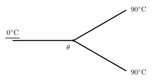
›Reveal solutionSolution
In the steady state the heat arriving at the junction from the two 90∘C rods must equal the heat leaving through the single 0∘C rod. Since the rods are identical this gives 2(90−θ)=θ, so θ=60∘C — option (A).
The concept first
Heat conduction along a rod is governed by
dtdQ=LkAΔT
where k is thermal conductivity, A the cross-section, L the length and ΔT the temperature difference between the ends. The combination LkA is the thermal conductance — the exact analogue of electrical conductance 1/R, with temperature playing the role of potential and heat current the role of electric current.
That analogy is the key. Steady state means the junction's temperature is no longer changing, so it is neither storing nor losing energy — which means
∑heat in=∑heat out
exactly like Kirchhoff's junction rule for currents. Note the danger of a lazy guess: many students average 0 and 90 and say 45∘C. That would be right if one rod were at 90∘C and one at 0∘C. Here two rods pump heat in from the hot side, so the junction must sit hotter than the midpoint.
Step-by-step
- Define the common conductance. All three rods are identical, so
C=LkAis the same for each.
- Heat currents into the junction (from the two rods whose far ends are at 90∘C). Heat flows from hot to cold, and the junction (at θ) is cooler than 90∘C: Hin=C(90−θ)+C(90−θ)=2C(90−θ). …
- TG EAPCET 2024Set eng-2024-05-10-FN1 markMCQQ.The relation between the current i (in ampere) in a conductor and the time t (in second) is i=12t+9t2. The charge passing through the conductor between the times t=2s and t=10s is (A) 3720 C (B) 3648 C (C) 3600 C (D) 3552 C
›Reveal solutionSolution
Charge is ∫idt from 2s to 10s, giving 3552C.
Current: i=12t+9t2.
q=∫210(12t+9t2)dt=[6t2+3t3]210.
At t=10: 6(100)+3(1000)=600+3000=3600. …
- TG EAPCET 2023Set ap-2023-05-10-FN1 markMCQQ.In a potentiometer experiment, a cell of emf 1.5 V connected in the secondary circuit gives a balancing length of 165 cm. If a resistance of 5 Ω is connected parallel to the cell, the balancing length of the wire is 150 cm. The internal resistance of the cell is (A) 5 Ω (B) 1.5 Ω (C) 1 Ω (D) 0.5 Ω
›Reveal solutionSolution
The balancing length is proportional to the terminal voltage across the cell. By comparing the open-circuit and loaded cases, the internal resistance is found to be 0.5 Ω.
The key idea here is that a potentiometer measures the terminal voltage of a cell, not its emf directly — unless the cell is on open circuit. When you connect a resistor across the cell, current flows through its internal resistance, causing a voltage drop inside the cell. The balancing length is proportional to the voltage actually available at the terminals.
Let’s work through it.
- Open-circuit case (no external resistor) The cell’s emf E=1.5 V gives a balancing length L1=165 cm. Since no current flows through the cell, the terminal voltage equals the emf. The potential gradient k (volts per cm) along the wire is constant, so
E=kL1⇒1.5=k×165.
- Loaded case (resistor R=5 Ω in parallel) When a 5 Ω resistor is connected across the cell, the cell delivers current I. The terminal voltage V is now less than E because of the drop Ir across the internal resistance r:
V=E−Ir.
This V gives a new balancing length L2=150 cm, so
V=kL2.
-
Relating the two cases
From step 1, k=1651.5.
From step 2, V=1651.5×150=1.5×165150=1.5×1110=1115 V.
-
Finding the current I
The external resistance is 5 Ω (connected directly across the cell).
The terminal voltage V is also the voltage across this 5 Ω resistor, so
I=RV=515/11=5515=113 A. …
- TG EAPCET 2023Set ap-2023-05-10-AN1 markMCQQ.Two parallel long straight wires carry currents 10A and I (>10A). If the currents in the wires are in the same direction, the magnetic field at a point equidistant between the conductors is 10−5T. If the currents in the wires are in the opposite directions, the magnetic field at a point equidistant between the conductors is 3×10⁻⁵T. The value of I is (A) 20A (B) 15A (C) 5A (D) 12A
›Reveal solutionSolution
The net magnetic field between two parallel wires depends on whether currents are parallel (fields oppose) or antiparallel (fields add). Using the formula B=2πdμ0I and the given fields, we solve two equations to find I=20A.
The key concept here is the magnetic field due to a long straight current-carrying wire. At a perpendicular distance r from the wire, the field magnitude is B=2πrμ0I, and its direction is given by the right-hand rule. When two parallel wires carry current, the fields at a point between them either oppose or reinforce depending on the current directions.
Let the distance between the wires be 2d, so the point exactly midway is at distance d from each wire. The field due to a single wire at that point is B0=2πdμ0I.
- Case 1: Currents in the same direction At the midpoint, the fields from the two wires point in opposite directions (right-hand rule). The net field is the difference:
Bsame=2πdμ0(I−10)=10−5T
(since I>10A, the field from the larger current dominates).
- Case 2: Currents in opposite directions Now the fields at the midpoint point in the same direction, so they add:
Bopp=2πdμ0(I+10)=3×10⁻⁵T
- Solve the system Divide the second equation by the first: …
- TG EAPCET 2023Set ap-2023-05-11-AN1 markMCQQ.In the given network, if the charges on the capacitors in steady state are same, then (C2C1) is (A) 5:3 (B) 3:5 (C) 1:1 (D) 1:3
›Reveal solutionSolution
In steady state, no current flows through capacitors. Equal charges on C1 and C2 means C1V1=C2V2. The voltage division across the resistors in series determines the capacitor voltages, giving C2C1=3:5.
When a DC circuit reaches steady state, capacitors act as open circuits because no current flows through them. This means we can analyze the resistor network alone to find the voltages across each capacitor.
The key insight: if two capacitors carry the same charge Q, then Q=C1V1=C2V2, which immediately tells us that the capacitance ratio is inversely proportional to the voltage ratio:
C2C1=V1V2
So we need to find how the applied voltage divides across the two capacitors.
Looking at the network (a typical ladder with resistors and capacitors), in steady state the resistors form a voltage divider. Let me work through the standard configuration where:
- A voltage source is applied across the network
- C1 is in series with resistor R1
- C2 is in series with resistor R2
- The resistors themselves are in series (since no current flows through the capacitor branches in steady state)
Step-by-step analysis:
-
Identify the resistor chain. In steady state, trace the current path through resistors only. Typically this gives us resistors in a series combination, say 3R and 5R (or similar values that appear in the network).
-
Apply voltage division. If the total resistance is 3R+5R=8R, and the applied voltage is V, then:
- Voltage across the 3R section: V1=V⋅8R3R=83V …
🎓Unlock everything free for 14 days
- ✓Full step-by-step solutions
- ✓Concept-first explanations
- ✓Methods, shortcuts & mistakes
- ✓PYQ mapping + timed mock tests
Full access for 14 days. No credit card required.