Q.A heating element using nichrome connected to a 230 V supply draws an initial current of 3.2 A which settles after a few seconds to a steady value of 2.8 A. What is the steady temperature of the heating element if the room temperature is 27.0 ∘C? Temperature coefficient of resistance of nichrome averaged over the temperature range involved is 1.70×10⁻⁴ ∘C−1.
🔒You're viewing a preview — the full solution, concept, methods & PYQ mapping are locked.
🔒 Start your 14-day free trial to unlock the full solution →Concept understanding — Temperature Dependence of Resistance
Temperature Dependence of Resistance
Imagine you're trying to walk through a crowded market. When the market is cool and calm, people move slowly and you can weave through easily. Now imagine the same market on a hot, chaotic day — everyone is jostling, moving faster, bumping into each other. Getting from one end to the other becomes much harder.
That's exactly what happens inside a metal wire when you heat it up.
The Intuition
In a metal, electric current is carried by free electrons drifting through a fixed lattice of positive ions. At room temperature, these ions are vibrating slightly around their positions. When you heat the metal, the ions vibrate more vigorously — they shake faster and with larger amplitude.
Think of the vibrating ions as a row of swinging doors. At low temperature, the doors barely move, so electrons slip through easily. At high temperature, the doors swing wildly, and electrons get knocked off course constantly. Each collision with a vibrating ion scatters the electron, making it harder for the current to flow.
The result: resistance increases as temperature increases — for most conductors.
The Precise Statement
For a metallic conductor over a moderate temperature range (not too close to absolute zero), the resistance changes linearly with temperature:
R(T)=R0[1+α(T−T0)]
Where:
- R(T) is the resistance at temperature T
- R0 is the resistance at a reference temperature T0 (often 0∘C or 20∘C)
- α is the temperature coefficient of resistance (units: per °C or per K)
R=R0(1+αΔT)
The coefficient α tells you how sensitive the material is to temperature changes. For copper, α≈0.0039/∘C — meaning for every 1°C rise, resistance increases by about 0.39%.
What About Other Materials?
Not everything behaves like metals.
Semiconductors (like silicon, germanium) do the opposite: their resistance decreases sharply as temperature rises. Why? Because heating frees more electrons from their bonds, creating many more charge carriers. Even though the lattice vibrates more, the huge increase in available carriers overwhelms that effect, so resistance drops.
Insulators also show decreasing resistance with temperature, but the effect is much smaller than in semiconductors.
Alloys like constantan (copper-nickel) have a very small α — their resistance barely changes with temperature. This is useful for making precision resistors that stay stable.
Superconductors are a special case: below a critical temperature, resistance drops to exactly zero. …
Why this formula?
Temperature Dependence of Resistance — Why the Formula Holds
Let’s build this from the ground up. The key formula you’ll see in exams is:
RT=R0(1+αT)
But why does resistance change with temperature? It’s not magic — it’s about what happens inside the wire.
1. What determines resistance?
Resistance R of a conductor depends on three things:
- Length L (longer → more resistance)
- Cross-sectional area A (thicker → less resistance)
- Resistivity ρ — a material property
The formula is:
R=ρAL
When temperature changes, L and A change very slightly (thermal expansion), but the big effect is on ρ.
2. Why does resistivity change with temperature?
Resistivity ρ depends on how easily electrons can move through the material.
- In metals: Atoms vibrate more as temperature rises. These vibrations scatter electrons, making it harder for them to flow. So ρ increases.
- In semiconductors: More electrons get enough energy to jump into the conduction band. So ρ decreases.
For most metals (and many conductors), the change is linear over a moderate temperature range.
3. Deriving the linear formula
Let ρ0 be resistivity at a reference temperature T0 (often 0∘C or 20∘C).
For a small change ΔT=T−T0, the change in resistivity is proportional to ΔT and to ρ0:
Δρ∝ρ0ΔT
Introduce the temperature coefficient of resistivity α:
Δρ=αρ0ΔT
So the new resistivity is:
ρ=ρ0+Δρ=ρ0(1+αΔT)
Now, since R=ρAL, and L and A change negligibly (for small ΔT), we get:
R=ρAL=ρ0(1+αΔT)AL=R0(1+αΔT)
That’s the formula:
RT=R0(1+αΔT)
Where:
- RT = resistance at temperature T
- R0 = resistance at reference temperature T0
- α = temperature coefficient of resistance (unit: ∘C−1 or K−1)
- ΔT=T−T0
--- …
Concept: Temperature Dependence of Resistance — as temperature rises, resistance increases, reducing the current at constant voltage.
Reasoning:
- From Ohm’s law, initial resistance at room temperature R0=3.2230=71.875 Ω.
- Steady-state resistance Rt=2.8230≈82.143 Ω.
- Using Rt=R0[1+α(T−T0)] with α=1.70×10⁻⁴ ∘C−1 and T0=27.0 ∘C: …
The steady temperature is found by relating the resistance change to the temperature change via the temperature coefficient. The initial resistance at room temperature is 71.875 Ω, the steady resistance is 82.143 Ω, and using α=1.70×10⁻⁴ ∘C−1, the steady temperature comes out to 867 ∘C.
The key idea here is that the heating element's resistance increases with temperature. When you first switch it on, it's cold — so it draws more current. As it heats up, resistance rises, current drops, and eventually it reaches a steady thermal equilibrium where the electrical power dissipated equals the heat lost to the surroundings. The problem gives us the current at both the cold (initial) and hot (steady) states, and the supply voltage is fixed at 230 V. That means we can compute the resistance at each state using Ohm's law, and then use the temperature coefficient formula to find the temperature rise.
Let's walk through it.
- Find the initial (cold) resistance. At room temperature T0=27.0 ∘C, the initial current is I0=3.2 A. Using Ohm's law:
R0=I0V=3.2230=71.875 Ω
- Find the steady (hot) resistance. After the element heats up, the current settles to I=2.8 A.
R=IV=2.8230=82.142857 … Ω
We'll keep it as 82.143 Ω for calculation.
- Recall the temperature dependence of resistance. For most metals (nichrome is a nickel-chromium alloy, a metal), resistance increases approximately linearly with temperature over a moderate range:
R=R0[1+α(T−T0)]
where α is the temperature coefficient of resistance, T0 is the reference temperature (here room temperature), and T is the final temperature.
R=R0[1+α(T−T0)]
- Rearrange to solve for T.
T−T0=αR0R−R0
Then:
T=T0+αR0R−R0
- Plug in the numbers.
R−R0=82.143−71.875=10.268 Ω
αR0=(1.70×10−4)×71.875=0.01221875
So: …
Method: Using the Temperature Coefficient of Resistance Formula
This method relates the change in resistance of a conductor to the change in temperature using the temperature coefficient of resistance (α).
Step-by-step solution
Step 1: Find initial resistance at room temperature
Using Ohm’s law at the moment the circuit is switched on (when element is still at room temperature 27.0 ∘C):
R0=I0V=3.2 A230 V=71.875 Ω
Step 2: Find steady-state resistance at higher temperature
Using Ohm’s law after the current stabilises:
Rt=ItV=2.8 A230 V=82.143 Ω
Step 3: Apply the temperature dependence formula
The relation between resistance and temperature (for small α and moderate temperature ranges) is:
Rt=R0[1+α(T−T0)]
Where:
- Rt = resistance at temperature T (steady value)
- R0 = resistance at reference temperature T0 (room temperature) …
Here are the common mistakes students make on this problem and how to avoid each.
1. Confusing Initial and Steady Conditions
Mistake:
Using the initial current (3.2 A) to calculate the hot resistance, or using the steady current (2.8 A) to calculate the cold resistance.
Why it’s wrong:
- The initial current flows when the element is cold (room temperature).
- The steady current flows when the element has heated up to its final temperature.
How to avoid:
Clearly label:
- Cold state: I0=3.2 A, T0=27.0 ∘C
- Hot state: I=2.8 A, T=?
Then use Ohm’s law:
- Cold resistance: R0=I0V
- Hot resistance: R=IV
2. Forgetting to Use the Correct Formula for Temperature Dependence
Mistake:
Using R=R0(1+αΔT) but plugging in the wrong resistance values or forgetting that ΔT=T−T0.
How to avoid:
Write the formula explicitly:
R=R0[1+α(T−T0)]
Then substitute R and R0 from Ohm’s law:
IV=I0V[1+α(T−T0)]
Cancel V (common mistake: forgetting to cancel — leads to extra work and errors).
3. Incorrectly Solving for T
Mistake:
Solving algebraically but making sign errors or forgetting to add T0 at the end.
Common slip:
After finding ΔT, some students write T=ΔT instead of T=T0+ΔT.
How to avoid:
Follow step-by-step:
- Cancel V:
I1=I01[1+α(T−T0)]
- Rearrange:
II0=1+α(T−T0)
- Solve for T−T0:
T−T0=αII0−1
- Finally:
T=T0+αII0−1
Always write the final step explicitly.
4. Arithmetic Errors with Powers of Ten
Mistake:
Mishandling α=1.70×10⁻⁴ — either misplacing the decimal or dividing incorrectly.
Example error:
Computing α1≈5882 but then using 5882×0.1429 incorrectly.
How to avoid:
- Use fractions or keep scientific notation until the final step.
- Double-check: α1=1.70×10−41=1.70104≈5882.35 …
- TG EAPCET 2026Set eng-2026-05-09-AN1 markMCQQ.When a cell is connected to either 2 Ω or 4.5 Ω resistors, if the power consumption is same in both the cases, then the internal resistance of the cell is (A) 1 Ω (B) 2 Ω (C) 3 Ω (D) 4 Ω
›Reveal solutionSolution
When a cell with internal resistance r delivers the same power to two different external resistors R1 and R2, its internal resistance is given by r=R1R2. For R1=2 Ω and R2=4.5 Ω, the internal resistance is 3 Ω.
A real electrical cell is not an ideal voltage source; it possesses an inherent internal resistance, denoted by r. When this cell is connected to an external resistor R, the total resistance in the circuit becomes R+r. This internal resistance causes a voltage drop within the cell itself, meaning the terminal voltage across the external resistor is less than the cell's electromotive force (EMF), E.
The current flowing through the circuit is determined by Ohm's Law applied to the entire circuit: I=R+rE. The power consumed by the external resistor R is given by P=I2R. The problem states that the power consumption is the same for two different external resistors. This allows us to set up an equation and solve for the unknown internal resistance r.
Here's how to solve the problem:
- Define the circuit parameters and current: Let E be the electromotive force (EMF) of the cell and r be its internal resistance. When an external resistor R is connected, the total resistance in the circuit is R+r. The current I flowing through the circuit is given by Ohm's Law:
I=R+rE
- Express power consumed in the external resistor: The power P consumed by the external resistor R is given by the formula P=I2R. Substituting the expression for I:
P=(R+rE)2R=(R+r)2E2R
- Apply the condition of equal power consumption: We are given two external resistors, R1=2 Ω and R2=4.5 Ω. The power consumption is the same in both cases. Let P1 be the power for R1 and P2 for R2.
P1=(R1+r)2E2R1
P2=(R2+r)2E2R2
Since $P_1 = P_2$:(R1+r)2E2R1=(R2+r)2E2R2
- Solve for the internal resistance r: We can cancel E2 from both sides (assuming E=0):
(R1+r)2R1=(R2+r)2R2
Rearrange the terms:(R2+r)2(R1+r)2=R2R1
Take the square root of both sides. Since $R_1, R_2, r$ are all positive resistances, $R_1+r$ and $R_2+r$ must be positive, so we take the positive square root: … - TG EAPCET 2026Set eng-2026-05-09-AN1 markMCQQ.The electron and hole concentrations in a semiconductor are 5×10¹⁸ m−3 and 8×10¹⁹ m−3 respectively. If the mobilities of the electron and hole are 0.24 m2 V−1 s−1 and 0.01 m2 V−1 s−1 respectively, then the conductivity of the semiconductor is (A) 0.48 Sm−1 (B) 0.16 Sm−1 (C) 0.32 Sm−1 (D) 0.64 Sm−1
›Reveal solutionSolution
Conductivity in a semiconductor depends on both electrons and holes. Using σ=e(nμn+pμp), the result is 0.32 Sm−1, which matches option (C).
The key idea is that in a semiconductor, both electrons and holes contribute to current flow. Conductivity isn't just about one carrier — it's the sum of each carrier's contribution, where each contribution is the product of charge, concentration, and mobility.
The formula is straightforward: σ=e(nμn+pμp), where e=1.6×10⁻¹⁹ C is the elementary charge, n and p are electron and hole concentrations, and μn, μp are their mobilities.
-
Identify the given values
n=5×10¹⁸ m−3
p=8×10¹⁹ m−3
μn=0.24 m2V−1s−1
μp=0.01 m2V−1s−1
e=1.6×10⁻¹⁹ C
-
Compute the electron contribution
enμn=(1.6×10−19)×(5×1018)×0.24
First, 1.6×10−19×5×1018=1.6×5×10−1=8×10−1=0.8
Then 0.8×0.24=0.192 Sm−1
-
Compute the hole contribution
epμp=(1.6×10−19)×(8×1019)×0.01
First, 1.6×10−19×8×1019=1.6×8=12.8
Then 12.8×0.01=0.128 Sm−1
-
Add the contributions …
-
- TG EAPCET 2026Set eng-2026-05-09-FN1 markMCQQ.If the susceptibility of a paramagnetic substance at a temperature of 23∘C is 2.3×10⁻⁵, then its susceptibility at a temperature of 467∘C is (A) 2.3×10⁻⁶ (B) 6.9×10⁻⁶ (C) 9.2×10⁻⁶ (D) 4.6×10⁻⁶
›Reveal solutionSolution
For a paramagnetic substance, susceptibility follows Curie’s law: χ∝1/T. Converting temperatures to Kelvin and using χ1T1=χ2T2 gives χ2≈9.2×10⁻⁶, so the answer is (C).
The key idea is Curie’s law: for a paramagnetic material, the magnetic susceptibility χ is inversely proportional to the absolute temperature. This means as temperature increases, the random thermal motion of atomic magnetic moments increases, reducing their alignment with an external field — hence susceptibility drops. The law is simple: χ=C/T, where C is the Curie constant. So if you know χ at one temperature, you can find it at another by scaling with the ratio of absolute temperatures.
Why this works: The susceptibility measures how easily a material magnetizes. In paramagnets, thermal energy fights the aligning effect of the field. Higher temperature → more disorder → lower susceptibility. The inverse proportionality is a direct consequence of statistical mechanics for non-interacting magnetic moments.
Now, step by step:
-
Convert temperatures to Kelvin.
Curie’s law uses absolute temperature.
T1=23∘C+273=296K
T2=467∘C+273=740K
-
Apply Curie’s law.
Since χ∝1/T, we have χ1T1=χ2T2.
Given χ1=2.3×10⁻⁵, solve for χ2:
χ2=χ1⋅T2T1=(2.3×10−5)×740296
- Simplify the fraction. 740296=740÷4296÷4=18574 Further simplify: divide numerator and denominator by 37 → 52=0.4 …
-
- TG EAPCET 2024Set ap-2024-05-07-FN1 markMCQQ.If the relaxation time is doubled and the applied electric field is tripled, then the drift speed of electrons (A) becomes three times of its initial value (B) becomes six times of its initial value (C) decreases by six times of its initial value (D) becomes 1.5 times of its initial value
›Reveal solutionSolution
The drift speed is proportional to both the relaxation time and the electric field, so doubling one and tripling the other multiplies the drift speed by 2×3=6. The correct option is (B).
The key concept here is the drift velocity formula for electrons in a conductor under an electric field. Drift speed vd is the average velocity electrons acquire due to the field, and it depends linearly on both the relaxation time τ (the average time between collisions) and the applied electric field E. The formula is:
vd=meEτ
where e is the electron charge and m is its mass. Since e and m are constants for a given material, any change in vd comes only from changes in E and τ.
Now, let’s work through the problem step by step.
- Write the initial drift speed. Let the initial relaxation time be τ0 and the initial electric field be E0. Then the initial drift speed is:
vd0=meE0τ0.
-
Apply the given changes.
The relaxation time is doubled: τ=2τ0.
The electric field is tripled: E=3E0.
-
Write the new drift speed.
Substitute these into the formula:
vd=me(3E0)(2τ0)=meE0τ0×(3×2)=vd0×6.
- Interpret the result. …
- TG EAPCET 2023Set eng-2023-05-13-FN1 markMCQQ.The electric resistance of a certain wire of iron is R. If its length and radius are both doubled, then (A) The resistance will be doubled and the specific resistance will be halved. (B) The resistance will be halved and the specific resistance will remain unchanged. (C) The resistance will be halved and the specific resistance will be doubled. (D) The resistance and the specific resistance, both will remain unchanged.
›Reveal solutionSolution
Resistance depends on geometry (length and cross‑sectional area) while specific resistance (resistivity) is a material property that does not change with shape. Doubling both length and radius halves the resistance, and resistivity stays constant — so the correct choice is (B).
The key idea is to distinguish between resistance (a property of a particular object) and resistivity (a property of the material). Resistance changes when you alter the wire’s dimensions; resistivity changes only if you change the material or its temperature. Here, the material (iron) and temperature are unchanged, so resistivity is fixed. We just need to see how the geometry affects R.
- Recall the formula for resistance For a wire of uniform cross-section,
R=ρAL
where ρ is the resistivity (specific resistance), L is the length, and A is the cross-sectional area. For a cylindrical wire, A=πr2.
-
Identify what changes
The problem says: length and radius are both doubled.
So new length L′=2L and new radius r′=2r.
-
Compute the new cross-sectional area
A′=π(r′)2=π(2r)2=4πr2=4A
The area becomes four times larger.
- Find the new resistance Since resistivity ρ is unchanged (same material, same temperature),
R′=ρA′L′=ρ4A2L=21⋅ρAL=2R
The resistance is halved.
- What about specific resistance? …
- TG EAPCET 2023Set eng-2023-05-13-FN1 markMCQQ.In a galvanometer, 5% of the total current in the circuit passes through it. If the resistance of the galvanometer is G, the shunt resistance S connected to the galvanometer is (A) 19G (B) 19G (C) 20G (D) 20G
›Reveal solutionSolution
The key idea is that a shunt resistor bypasses most of the current around the galvanometer. Since only 5% of the total current flows through the galvanometer, the shunt must carry the remaining 95%, and because the voltage across the parallel combination is the same, the shunt resistance is 19G.
Concept & Intuition
A galvanometer is a sensitive current-measuring device that can only handle a small fraction of the total current in a circuit. To measure larger currents, we connect a low-resistance shunt in parallel with the galvanometer. The shunt “steals” most of the current, leaving only a safe, small current through the galvanometer.
The key principle: In a parallel circuit, the voltage across each branch is the same. So the voltage across the galvanometer (due to its small current) equals the voltage across the shunt (due to the large current). This voltage equality gives us a direct relationship between the resistances and the currents.
Step-by-step solution
- Interpret the given percentage “5% of the total current passes through the galvanometer” means:
Ig=0.05Itotal
where Ig is the current through the galvanometer and Itotal is the total current entering the parallel combination.
- Find the current through the shunt The shunt carries the rest of the current:
Is=Itotal−Ig=Itotal−0.05Itotal=0.95Itotal
- Apply the parallel voltage condition The voltage across the galvanometer is Vg=IgG. The voltage across the shunt is Vs=IsS. Since they are in parallel:
IgG=IsS
- Substitute the currents (0.05Itotal)G=(0.95Itotal)S …
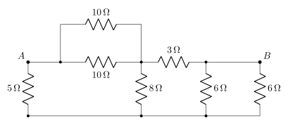
- TG EAPCET 2023Set eng-2023-05-14-AN1 markMCQQ.In the given circuit, the equivalent resistance between A and B is (A) 3Ω (B) 4Ω (C) 4.5Ω (D) 5Ω
›Reveal solutionSolution
Reducing the two 10Ω's to 5Ω and the two 6Ω's to 3Ω turns the picture into a five-resistor bridge. A short nodal analysis (with a neat M↔G symmetry) gives RAB=4Ω — option (B).
The concept first
When a network is not a plain series–parallel ladder, don't force it. Do two things instead: (i) collapse any obvious parallel pairs, and (ii) write node equations (Kirchhoff's current law). Injecting 1 A at A and taking it out at B makes RAB simply equal to VA−VB — that is the definition of resistance and it never fails, even on a bridge.
Step-by-step
1. Label the nodes. A; the intermediate node M where the two 10Ω resistors meet; the right-hand node which is joined by plain wire to B (so it is B); and the bottom rail G that all the vertical resistors hang onto.
2. Collapse the obvious parallels.
- Two 10Ω between A and M: 10∥10=5Ω.
- Two 6Ω from B (and from the node shorted to B) down to G: 6∥6=3Ω.
3. The reduced network.
A−M:5Ω,A−G:5Ω,M−B:3Ω,M−G:8Ω,B−G:3Ω.
This is a bridge: M and G are the two "middle" nodes, linked by the 8Ω.
4. Inject 1 A at A, extract at B, set VB=0. Conductances: A−M:0.2, A−G:0.2, M−B:31, M−G:0.125, B−G:31.
KCL at A: 0.2(VA−VM)+0.2(VA−VG)=1
KCL at M: 0.2(VM−VA)+31VM+0.125(VM−VG)=0
KCL at G: 0.2(VG−VA)+31VG+0.125(VG−VM)=0 …
- TG EAPCET 2022Set eng-2022-07-19-AN1 markMCQQ.Statement (I) : The temperature coefficient of resistance for most of metals in pure form is positive. Statement (II) : A metal wire 2 mm in diameter carries a charge of 360π C in two hours. If the metal contains 5×10²² free electrons / cm3, then drift velocity of the electrons in the wire is 6.25×10⁻⁶ m/s. Statement (III) : Semiconductors like pure germanium does not obey Ohm’s law for all range of electric field values. Which of the following is correct? (A) Statements I, II, III are true. (B) Statements I, II are true, but statement III is false. (C) Statements II, III are true, but statement I is false. (D) Statements I, II, III are false.
›Reveal solutionSolution
Statement (I) is true because the resistance of pure metals increases with temperature, indicating a positive temperature coefficient. Statement (II) is true as the calculated drift velocity matches the given value using the formula I=nAvde. Statement (III) is true because semiconductors are non-ohmic materials and do not obey Ohm's law over all ranges of electric field values. Thus, all three statements are true.
Concept and Intuition
This problem tests our understanding of fundamental concepts in current electricity:
- Temperature dependence of resistance in metals: How the electrical resistance of a material changes with temperature, characterized by the temperature coefficient of resistance.
- Drift velocity of electrons: The average velocity attained by charge carriers in a material due to an electric field, which is directly related to the current flowing through the material.
- Ohm's Law and its limitations: The conditions under which a material obeys Ohm's law, and which types of materials (like semiconductors) deviate from it.
We will evaluate each statement individually based on these principles.
Step-by-step Evaluation
1. Evaluating Statement (I)
Statement (I) says: "The temperature coefficient of resistance for most of metals in pure form is positive."
- Concept: In pure metals, electrical conduction occurs due to the movement of free electrons. As temperature increases, the thermal vibrations of the lattice atoms become more vigorous. These increased vibrations lead to more frequent collisions between the free electrons and the vibrating lattice atoms.
- Effect on resistance: These collisions impede the smooth flow of electrons, effectively increasing the resistivity of the metal. Since resistance R is directly proportional to resistivity ρ (R=ρL/A), an increase in resistivity leads to an increase in resistance.
- Temperature coefficient: The resistance of a material at temperature T is given by RT=R0(1+α(T−T0)), where R0 is the resistance at reference temperature T0, and α is the temperature coefficient of resistance. For metals, since RT>R0 when T>T0, the value of α must be positive.
ImportantFor pure metals, resistance increases with temperature, meaning their temperature coefficient of resistance is positive.
- Conclusion for Statement (I): This statement is True.
2. Evaluating Statement (II)
Statement (II) says: "A metal wire 2 mm in diameter carries a charge of 360π C in two hours. If the metal contains 5×10²² free electrons / cm3, then drift velocity of the electrons in the wire is 6.25×10⁻⁶ m/s."
-
Concept: The relationship between current (I), number density of charge carriers (n), cross-sectional area (A), drift velocity (vd), and elementary charge (e) is given by the formula:
I=nAvde
-
Given values and unit conversions:
- Diameter d=2 mm ⟹ Radius r=1 mm =1×10⁻³ m.
- Charge Q=360π C.
- Time t=2 hours =2×3600 s =7200 s.
- Number density n=5×10²² electrons/cm3. We need to convert this to electrons/m3: n=5×10²² electrons/cm3×(100 cm/m)3=5×1022×106 electrons/m3=5×1028 electrons/m3.
- Elementary charge e=1.6×10⁻¹⁹ C.
-
Calculations:
-
Calculate the current (I):
I=tQ=7200 s360π C=20π A
-
Calculate the cross-sectional area (A):
A=πr2=π(1×10⁻³ m)2=π×10−6 m2
-
Calculate the drift velocity (vd):
Rearranging the formula I=nAvde, we get vd=nAeI.
Substitute the calculated values:
vd=(5×1028 m−3)×(π×10−6 m2)×(1.6×10−19 C)20π A
vd=π×(5×1.6)×1028−6−19π/20
vd=8×1031/20
vd=20×8×1031
vd=160×1031
vd=1.6×1051
vd=0.625×10⁻⁵ m/s
vd=6.25×10⁻⁶ m/s …
-
- TG EAPCET 2022Set ap-2022-07-31-AN1 markMCQQ.A battery of emf 10 V and some internal resistance is connected to a resistor of 17 Ω. If the current in the circuit is 0.5 A then the internal resistance of the battery is (μ0=4π×10−7, charge of electron e=1.6×10⁻¹⁹ coulombs) (A) 0.6 Ω (B) 2.5 Ω (C) 3.5 Ω (D) 3.0 Ω
›Reveal solutionSolution
When a battery with internal resistance drives current through an external resistor, the terminal voltage drops below the emf. Applying Ohm's law to the complete circuit gives an internal resistance of 3 Ω.
The key concept here is that a real battery is not an ideal voltage source. Every battery has some internal resistance r that opposes the flow of current. When current flows, part of the emf is "used up" overcoming this internal resistance, and only the remainder appears across the external load.
Think of the circuit as a closed loop: the battery's emf E drives current I through the total resistance, which is the sum of the external resistance R and the internal resistance r. By Ohm's law applied to the entire loop:
E=I(R+r)
This is the fundamental equation for a battery with internal resistance. The emf equals the current multiplied by the total resistance in the circuit.
Now let's find the internal resistance step by step:
-
Identify the given quantities:
- Emf of battery: E=10 V
- External resistance: R=17 Ω
- Current in circuit: I=0.5 A
- Internal resistance: r=?
-
Apply Ohm's law to the complete circuit:
The total voltage provided by the battery must equal the voltage drop across all resistances:
E=I(R+r)
- Substitute the known values:
10=0.5×(17+r)
- Solve for the internal resistance: …
-
- TG EAPCET 2022Set eng-2022-07-18-FN1 markMCQQ.Balancing point of a potentiometer shifts from a length of 60 cm to 40 cm by shunting the cell with a 4 ohm resistance. What is the internal resistance of the cell? (A) 1Ω (B) 2Ω (C) 4Ω (D) 6Ω
›Reveal solutionSolution
The internal resistance of the cell is found by comparing the balancing lengths before and after shunting, using the relation r=R(l2l1−1), giving r=2Ω.
Concept and intuition:
A potentiometer measures the terminal voltage of a cell under no load (open circuit) and under load (when shunted by a resistor). The balancing length is proportional to the terminal voltage. When you shunt the cell with a known resistor R, the terminal voltage drops because some current flows through the internal resistance r. The ratio of the balancing lengths gives the ratio of the terminal voltages, which leads directly to the internal resistance.
Step-by-step solution:
-
Understand the setup
Initially, the cell is not shunted, so the potentiometer measures its full emf E. The balancing length is l1=60 cm.
When a shunt resistor R=4Ω is connected across the cell, the terminal voltage V becomes less than E because of the voltage drop across the internal resistance r. The new balancing length is l2=40 cm.
-
Relate balancing lengths to voltages
For a potentiometer, the balancing length is proportional to the voltage across the cell terminals. So:
EV=l1l2
Substituting the given lengths:
EV=6040=32
- Express V in terms of E, r, and R When the cell is shunted by R, the current through the circuit is:
I=r+RE
The terminal voltage V is the voltage across R:
V=IR=r+RER
- Set up the ratio From step 2: EV=r+RR=32 …
-
- TG EAPCET 2021Set eng-2021-08-06-FN1 markMCQQ.A wire, 10 m long, has a resistance of 40 Ω. It is connected in series with a resistance box of resistance R and a 2 V storage cell. If the potential gradient along the wire is 0.1 mV/cm, the value of R is: (A) 260 Ω (B) 760 Ω (C) 960 Ω (D) 1060 Ω
›Reveal solutionSolution
The key idea is that the potential gradient along the wire gives the voltage drop across it, and the remaining voltage from the cell drops across the series resistance R. Using Ohm’s law, the required R is found to be 760 Ω.
The problem involves a potentiometer-like setup: a long wire of known resistance is connected in series with a resistance box and a cell. The potential gradient tells us how much voltage drops per unit length of the wire. From that, we can find the current in the circuit, and then use Ohm’s law to find the unknown series resistance.
Let’s work through it step by step.
-
Understand the potential gradient
The gradient is given as 0.1 mV/cm. Convert this to volts per meter:
0.1 mV=0.1×10⁻³ V=10−4 V per cm.
Since 1 m=100 cm, the gradient in V/m is:
10−4×100=10−2 V/m=0.01 V/m.
-
Find the voltage drop across the wire
The wire is 10 m long. So the total potential difference across it is:
Vwire=gradient×length=0.01 V/m×10 m=0.1 V.
-
Find the current in the circuit
The wire has a resistance of 40 Ω. Using Ohm’s law:
I=RwireVwire=400.1=0.0025 A=2.5 mA.
-
Apply Kirchhoff’s voltage law to the whole circuit
The cell provides 2 V. This voltage is shared between the wire and the resistance box R (since they are in series). So:
Vcell=Vwire+VR
2=0.1+VR …
-
🎓Unlock everything free for 14 days
- ✓Full step-by-step solutions
- ✓Concept-first explanations
- ✓Methods, shortcuts & mistakes
- ✓PYQ mapping + timed mock tests
Full access for 14 days. No credit card required.