Physics · Ch 2 — Ray Optics and Optical Instruments
Total Internal Reflection in Nature and its Technological Applications
Total Internal Reflection in Nature and its Technological Applications
Total Internal Reflection in Nature and Technology
Total internal reflection (TIR) is not just a textbook phenomenon — it is the working principle behind several everyday devices and natural effects. This section explores two major applications: prisms and optical fibres.
1. Prisms Using Total Internal Reflection
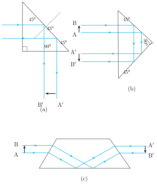
Prisms can bend light by 90° or 180° using TIR, without needing a mirror coating. They also invert images without changing their size.
- Condition for TIR in a prism: The light must strike the internal surface at an angle greater than the critical angle for the prism material.
- For a prism to bend light by 90° or 180°, the critical angle must be less than 45°.
- From Table 9.1 (NCERT), both crown glass and dense flint glass satisfy , so they work perfectly.
Why this works:
When light enters a prism at a suitable angle, it hits the hypotenuse face at an angle larger than , causing total internal reflection. The light then exits in a new direction.
2. Optical Fibres
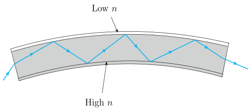
Optical fibres are thin, flexible strands of glass or quartz that transmit light signals over long distances using repeated total internal reflections.
Structure of an optical fibre:
- Core: Central part, made of material with higher refractive index ().
- Cladding: Outer layer, made of material with lower refractive index ().
Working principle:
- Light enters the fibre at one end at a suitable angle (greater than the critical angle for the core-cladding interface).
- It undergoes total internal reflection repeatedly along the fibre's length.
- Because each reflection is total, no appreciable light is lost — the signal remains strong even over kilometres.
Key condition for TIR in fibres:
The angle of incidence at the core-cladding boundary must always be greater than the critical angle , where:
Here:
- = refractive index of core (higher)
- = refractive index of cladding (lower)
Advantages:
- Even if the fibre is bent, light continues to travel by TIR — the fibre acts as an optical pipe.
- Bundles of fibres are used for: …
Drawn by us to help you understand the concept clearly, and verified to make sure it's accurate. For exams, practice from your textbook's own diagram.
What the Figure Shows
The figure presents three separate diagrams of a right-angled (45°-45°-90°) glass prism, each illustrating a different use of total internal reflection. In every case, the prism is drawn with a right-angle mark at the 90° corner, and the two acute angles are 45° each. Arrows indicate the path of a light ray entering and leaving the prism.
-
Panel (a): A ray enters the prism through one of the short faces normally (perpendicular to the surface). It travels straight to the hypotenuse (the long face), where it strikes at an angle of 45° to the normal. Since 45° is greater than the critical angle for glass (about 42° for crown glass), the ray undergoes total internal reflection at the hypotenuse. It then exits through the other short face, having been turned through 90° from its original direction. The label "90°" appears near the bend.
-
Panel (b): A ray enters normally through one short face, travels to the opposite short face, and undergoes total internal reflection there. The reflected ray then strikes the other short face and again undergoes total internal reflection. After these two reflections, the ray emerges from the same face it entered, traveling back exactly opposite to its original direction — a 180° turn (retro-reflection). The label "180°" marks this reversal.
-
Panel (c): A ray enters normally through one short face, passes through the prism without any internal reflection, and exits through the opposite short face. The ray's direction is unchanged, but the image formed by the prism is inverted top-to-bottom (upside down) while its size remains the same. This inversion occurs because the prism acts like a thick lens, flipping the image due to the geometry of refraction at the two faces.
Physical Idea Taught
The key concept is that total internal reflection can be used to redirect light efficiently without the loss of intensity that occurs with ordinary mirrors (which absorb some light). The prism's 45° angles are chosen so that the ray strikes the reflecting surface at exactly 45°, which is above the critical angle for common glasses. This ensures 100% reflection at the interface. The three configurations demonstrate practical applications: bending light by 90° (as in periscopes), reversing light by 180° (as in retroreflectors), and inverting an image without changing its size (as in binoculars or camera viewfinders).
Key Formula and Its Explanation
The condition for total internal reflection is that the angle of incidence inside the denser medium must exceed the critical angle , given by:
where:
- is the refractive index of the denser medium (the prism glass, e.g., crown glass with ),
- is the refractive index of the rarer medium (air, with ). …
Drawn by us to help you understand the concept clearly, and verified to make sure it's accurate. For exams, practice from your textbook's own diagram.
Figure 9.14: Optical Fibre and Total Internal Reflection
The figure shows a long, slightly bent tube representing an optical fibre. The tube has two distinct layers: a central core (the inner, darker region) and an outer cladding (the lighter surrounding layer). A single light ray enters the fibre from the left end at a specific angle. Inside the core, the ray travels in a zig-zag path, repeatedly striking the core–cladding boundary. At each strike, the ray is reflected back into the core — this is labelled as total internal reflection. The ray continues this bouncing path along the entire length of the fibre and finally emerges from the far right end.
Physical Idea Taught
The diagram demonstrates how an optical fibre guides light over long distances with minimal loss. The key principle is total internal reflection: when light travelling in a medium of higher refractive index (the core) strikes the boundary with a medium of lower refractive index (the cladding) at an angle greater than the critical angle, it is completely reflected back into the core. No light escapes into the cladding, so the signal intensity is preserved. Even if the fibre is bent, as shown in the figure, the ray continues to undergo total internal reflection as long as the angle of incidence at each bounce exceeds the critical angle.
Key Formula Developed with This Figure
The condition for total internal reflection is derived from Snell’s law. When light passes from the core (refractive index ) to the cladding (refractive index , with ), the critical angle is given by:
For total internal reflection to occur at each bounce, the angle of incidence at the core–cladding boundary must satisfy:
where:
- = refractive index of the core material (higher value)
- = refractive index of the cladding material (lower value)
- = critical angle for the core–cladding interface
- = angle of incidence of the ray at the boundary (measured from the normal to the surface) …