Q.The resistance of 8 ohm and inductive reactance of 6 ohm are connected in series in an alternating current circuit. The impedance of circuit will be:
(A) 2 ohm
(B) 14 ohm
(C) 142 ohm
(D) 10 ohm
🔒You're viewing a preview — the full solution, concept, methods & PYQ mapping are locked.
🔒 Start your 14-day free trial to unlock the full solution →Concept understanding — AC Circuit Analysis
AC Circuit Analysis: A First Look
The Core Intuition
Imagine you're pushing a child on a swing. You don't push once and stop — you push rhythmically, back and forth, matching the swing's natural motion. That rhythmic push is like Alternating Current (AC).
In a DC circuit (like a battery), current flows in one direction — steady, like a river. In an AC circuit, the current reverses direction many times per second — like the swing going forward, then backward, then forward again.
Why does this matter? Because when current keeps changing direction, components like coils and capacitors behave very differently than they do with steady DC. They "resist" change, store energy, and create phase shifts — the current and voltage don't peak at the same time.
The Precise Statement
AC Circuit Analysis is the study of how voltage, current, and power behave in circuits where the source voltage varies sinusoidally with time:
v(t)=Vmsin(ωt+ϕ)
Where:
- Vm = peak voltage (maximum value)
- ω = angular frequency (2πf, where f is frequency in Hz)
- ϕ = phase angle (where the wave starts)
- t = time
The current in such a circuit is also sinusoidal, but may be shifted in time relative to the voltage:
i(t)=Imsin(ωt+ϕ−θ)
Here θ is the phase difference between voltage and current.
Three Key Behaviors (The "Why")
1. Resistor (R) — No phase shift
- Voltage and current rise and fall together
- v(t)=R⋅i(t) holds at every instant
- Phase difference θ=0∘
2. Inductor (L) — Current lags voltage
- An inductor resists changes in current
- When voltage peaks, current is still catching up
- Current lags voltage by 90∘ (θ=+90∘)
- Opposition to AC is called inductive reactance: XL=ωL=2πfL
3. Capacitor (C) — Current leads voltage
- A capacitor resists changes in voltage
- When voltage is zero, current is maximum (charging)
- Current leads voltage by 90∘ (θ=−90∘)
- Opposition to AC is called capacitive reactance: XC=ωC1=2πfC1
The Big Idea: Impedance
Instead of just "resistance," AC circuits use impedance (Z), which combines:
- Resistance (R) — energy loss (real part)
- Reactance (X) — energy storage (imaginary part)
Z=R+jX
Where j=−1 (engineers use j instead of i to avoid confusion with current).
Ohm's Law for AC:
V=I⋅Z
But here V and I are phasors — complex numbers that represent magnitude and phase.
Why This Matters for Exams
| Concept | What to remember |
|---|---|
| RMS value | Vrms=2Vm — the "effective" DC equivalent |
| Power | P=VrmsIrmscosθ — only the in-phase part does real work |
| Resonance | When XL=XC, impedance is minimum, current is maximum |
In a series AC circuit the resistance and the reactance combine like the two perpendicular sides of a right triangle, so the impedance is the square root of the sum of their squares. …
Impedance of a series R–L circuit is Z=R2+XL2=64+36=10 Ω — option (D).
Concept. In a series AC circuit the resistance R and reactance XL add like the two perpendicular sides of a right triangle (because the voltage across R is in phase with the current while the voltage across L leads it by 90∘). The magnitude of the total opposition, the impedance, is the hypotenuse: …
Showing the 12 most recent of 26 on this concept.
- CBSE 2026Set DS1 markQ.The variation between V and I with time (t) in two alternative circuits is shown in the following graphs. Which one of the curves of circuit is capacitive and which one is resistive?
›Reveal solutionSolution
In-phase V and I ⇒ resistive circuit; current leading voltage by 90∘ ⇒ capacitive circuit.
Concept. The phase relation between voltage and current identifies the circuit element:
- Pure resistor: current is in phase with voltage — both reach their maxima and zeros at the same instant.
- Pure capacitor: current leads the voltage by a quarter cycle (90∘, i.e. π/2) — the current curve peaks before the voltage curve.
Reading the graphs.
- In the left graph the current curve I and the voltage curve V rise together and reach their peaks at the same time — they are in phase → this is the resistive circuit. …
- CBSE 2026Set ANNUAL1 markQ.Can a battery be charged by using alternating current? Write the reason.
›Reveal solutionSolution
Charging a battery needs current flowing in one fixed direction; AC reverses direction every half-cycle, so used directly it undoes on the second half-cycle whatever it did on the first.
Charging a cell/battery means forcing conventional current into it against its own e.m.f. so chemical energy is stored, which requires a steady, one-directional (DC) current. Alternating current changes direction periodically (e.g. every 1/100 s for 50 Hz mains), so during one half-cycle it would tend to charge the battery, but during the very next half-cycle the reversed current would discharge it by an equal amount — the net effect over a full cycle is essentially zero charging, and repeatedly reversing cu …
- CBSE 2026Set ANNUAL1 markMCQQ.The time taken by an AC of frequency 50 Hz to reach from zero to the maximum value is(a) 50×10−3 s(b) 5×10⁻³ s(c) 1×10⁻³ s(d) 2×10⁻³ s
›Reveal solutionSolution
An alternating current varies as i=I0sinωt. It starts at zero and first reaches its maximum (I0) after one quarter of a full cycle, i.e. t=T/4.
Step 1 — Find the time period
T=f1=50 Hz1=0.02 s=20×10−3 s
Step 2 — Express the current as a function of time
Since the current is zero at t=0 and increases from there, it is described by
i(t)=I0sin(ωt),ω=T2π
i(t) reaches its maximum value I0 when sinωt=1, i.e. when
…
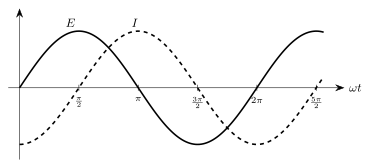
- CBSE 2026Set ANNUAL1 markMCQQ.The figure given below shows the phase relationship between voltage E and current I. Which of the following statements is true?(a) This phase relationship is for a resistor when AC is passed through it.(b) This phase relationship is for a capacitor when AC is passed through it.(c) This phase relationship is for an inductor when AC is passed through it.(d) This phase relationship is for an L-C-R circuit.
›Reveal solutionSolution
The graph shows current lagging voltage by a quarter cycle (π/2). Comparing this to the known phase behaviour of R, L, C elements in AC circuits identifies the element as a pure inductor.
Phase relationships of R, L, C in AC circuits (recap)
- Pure resistor: V=IR at every instant, so I and V (or E) are always in phase (zero phase difference).
- Pure capacitor: I=CdV/dt; when V=V0sinωt, I=ωCV0cosωt=ωCV0sin(ωt+π/2) — current leads voltage by π/2.
- Pure inductor: V=LdI/dt; when I=I0sinωt, V=ωLI0cosωt=ωLI0sin(ωt+π/2) — equivalently, current lags voltage by π/2: I=I0sin(ωt−π/2) relative to V=V0sinωt.
- Series L-C-R circuit: the phase difference ϕ between V and I is given by tanϕ=(XL−XC)/R, which generally lies between 0 and π/2 (not exactly π/2) unless R=0.
Reading the graph
…
- CBSE 2025Set 55/4/11 markMCQQ.Assertion (A): A series LCR circuit behaves as a pure resistive circuit at resonance. Reason (R): At resonance, XL=XC, which gives ω=LC1. (A) Both Assertion (A) and Reason (R) are true and Reason (R) is the correct explanation of the Assertion (A). (B) Both Assertion (A) and Reason (R) are true, but Reason (R) is not the correct explanation of the Assertion (A). (C) Assertion (A) is true, but Reason (R) is false. (D) Both Assertion (A) and Reason (R) are false.
›Reveal solutionSolution
At resonance, the inductive and capacitive reactances cancel exactly, making the circuit purely resistive. The reason correctly states the condition XL=XC and the resonant frequency formula, so both are true and the reason is the correct explanation.
Concept and Intuition
In a series LCR circuit, the total impedance is Z=R+j(XL−XC), where XL=ωL and XC=1/(ωC). The phase angle ϕ between voltage and current is given by tanϕ=(XL−XC)/R. For the circuit to behave as a pure resistor, the imaginary part must vanish — that is, XL=XC. This condition defines resonance. When it holds, the impedance is minimum (Z=R), current is maximum, and voltage and current are in phase (ϕ=0). The reason correctly identifies this condition and the resulting angular frequency ω=1/LC.
Watch outA common mistake is to think that at resonance the circuit has zero impedance. It does not — the impedance equals R, which is purely resistive but not zero (unless R=0). The key is that the reactive parts cancel, not that reactance disappears.
Step-by-step reasoning
-
Assertion (A) states that a series LCR circuit behaves as a pure resistive circuit at resonance. This is true because at resonance, XL=XC, so the net reactance is zero. The impedance becomes Z=R+j0=R, a purely real quantity. Hence voltage and current are in phase, exactly as in a resistor.
-
Reason (R) states that at resonance, XL=XC, which gives ω=1/LC. This is also true. Setting XL=XC:
ωL=ωC1⇒ω2=LC1⇒ω=LC1
(taking the positive root, since frequency is positive). …
-
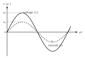
- CBSE 2025Set X11 markMCQQ.The variation of voltage and current through an a.c. circuit with time is as shown in the figure. Along with the a.c. source, the circuit :(a) has a series combination of resistance and capacitance(b) has only inductance(c) has only capacitance(d) may have only resistance or may have a suitable series combination of inductance (L), capacitance (C) and resistance (R)
›Reveal solutionSolution
The printed graph shows voltage v and current i crossing zero together and peaking at the same ωt — they are in phase (phase difference ϕ=0). A zero phase angle means the net reactance is zero, which is true for a pure resistor or for a series LCR circuit at resonance. Hence the correct choice is (d).
What the graph tells us
Both sinusoids start at the origin, rise together, reach their peaks (v0 and i0) at the same instant, and cross the ωt axis at the same points. So:
v=v0sin(ωt),i=i0sin(ωt)
The phase difference between voltage and current is ϕ=0. (Only the amplitudes differ, v0>i0, which is irrelevant to the phase.)
Linking phase to the circuit
For a general a.c. circuit, tanϕ=RXL−XC. A phase difference of zero requires XL−XC=0, i.e. the net reactance vanishes. This can happen in two ways:
- Only resistance (R): there is no reactance at all, so v and i are always in phase.
- A series LCR circuit at resonance: here XL=XC, the reactances cancel, the impedance becomes purely resistive (Z=R), and v and i come back into phase.
Why the other options are wrong …
- CBSE 2025Set JS1 markMCQQ.The resistance of 8 ohm and inductive reactance of 6 ohm are connected in series in an alternating current circuit. The impedance of circuit will be: (A) 2 ohm (B) 14 ohm (C) 142 ohm (D) 10 ohm
›Reveal solutionSolution
Impedance of a series R–L circuit is Z=R2+XL2=64+36=10 Ω — option (D).
Concept. In a series AC circuit the resistance R and reactance XL add like the two perpendicular sides of a right triangle (because the voltage across R is in phase with the current while the voltage across L leads it by 90∘). The magnitude of the total opposition, the impedance, is the hypotenuse: …
- CBSE 2025Set JS1 markQ.Voltage (V) equation in an alternating current circuit is represented by V=40sin(100πt) volt. Here t is in second. Draw the time-voltage graph for one cycle with proper scale.
›Reveal solutionSolution
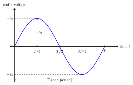
Figure — A single sine curve of emf/voltage vs time Peak 40 V, period T=0.02 s (20 ms); plot a sine curve rising to +40 V at t=5 ms, back to 0 at 10 ms, down to −40 V at 15 ms, and returning to 0 at 20 ms.
Concept. For V=V0sin(ωt), the amplitude is V0 and the angular frequency is ω, giving period T=ω2π.
Read off the values.
V0=40 V,ω=100π rad s−1,
T=ω2π=100π2π=0.02 s=20 ms,f=T1=50 Hz.
Key points of one cycle (scale: x-axis 1 div =5 ms, y-axis 1 div =10 V):
| t (ms) | 0 | 5 | 10 | 15 | 20 | …
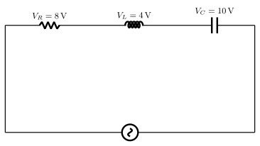
- CBSE 2025Set ANNUAL1 markMCQQ.The value of alternating voltage in the following circuit is(a) 2 V(b) 4 V(c) 8 V(d) 10 V
›Reveal solutionSolution
In a series R-L-C a.c. circuit, VL and VC are 180 degrees out of phase with each other and both are 90 degrees out of phase with VR, so the source voltage is the phasor sum V=VR2+(VL−VC)2, not the plain arithmetic sum.
In a series a.c. circuit, the voltage across R is in phase with the current, the voltage across L leads the current by 90∘, and the voltage across C lags the current by 90∘ (VL and VC are therefore antiphase to each other). The applied (source) voltage is t …
- CBSE 2025Set ANNUAL1 markMCQQ.The unit of reactance is(a) ohm(b) mho(c) farad(d) ampere
›Reveal solutionSolution
Reactance X (whether inductive, XL = wL, or capacitive, XC = 1/wC) has the same dimensions as resistance, since it appears in V = IX exactly like Ohm's law.
…
- CBSE 2025Set ANNUAL1 markQ.The equation of an alternating current is I=50sin100t. Find the frequency. OR A 100 hertz alternating current is flowing in a 14 mH coil. Find its reactance.
›Reveal solutionSolution
Reading off ω from the given equation and using f=ω/2π gives about 15.9 Hz; for the alternative, XL=2πfL gives about 8.8 Ω.
Finding the frequency
The standard form of an alternating current is
I=I0sin(ωt)
Comparing with the given equation I=50sin(100t):
ω=100 rad/s
Since ω=2πf,
f=2πω=2π100≈15.9 Hz
…
- CBSE 2024Set 55/2/11 markMCQQ.A resistor and an ideal inductor are connected in series to a 1002 V, 50 Hz ac source. When a voltmeter is connected across the resistor or the inductor, it shows the same reading. The reading of the voltmeter is : (A) 1002 V (B) 100 V (C) 502 V (D) 50 V
›Reveal solutionSolution
In a series RL circuit, equal voltmeter readings across R and L imply equal voltage drops, which forces the impedance triangle to be isosceles — the common reading is 100 V.
The key idea here is that the voltmeter reads the RMS voltage across each component. For a series RL circuit driven by an AC source, the source voltage Vs is the phasor sum of VR and VL, not the arithmetic sum — because the resistor voltage and inductor voltage are 90∘ out of phase.
When the voltmeter shows the same reading across R and L, we have VR=VL=V (say). The source RMS voltage is given as 1002 V. The phasor relationship is:
Vs2=VR2+VL2=V2+V2=2V2
So V=2Vs=21002=100 V.
That is the reading on the voltmeter — 100 V.
-
Understand the circuit and the source.
The source is 1002 V, 50 Hz AC. The voltmeter reads RMS values (standard for AC voltmeters). The resistor and ideal inductor are in series.
-
Phase relationship.
In a series RL circuit, current I is common. Voltage across resistor VR=IR is in phase with current. Voltage across inductor VL=IXL leads current by 90∘. So VR and VL are perpendicular phasors.
-
Given condition: equal readings.
The voltmeter reads the same value across R and L. So VR=VL=V (say).
-
Apply phasor addition for the source voltage.
The source RMS voltage Vs is the magnitude of the phasor sum:
Vs=VR2+VL2=V2+V2=V2
- Solve for V. …
-
🎓Unlock everything free for 14 days
- ✓Full step-by-step solutions
- ✓Concept-first explanations
- ✓Methods, shortcuts & mistakes
- ✓PYQ mapping + timed mock tests
Full access for 14 days. No credit card required.