Q.(a) Discuss the behaviour of an inductor connected to
You're viewing a preview — the full solution, concept, methods & PYQ mapping are locked.
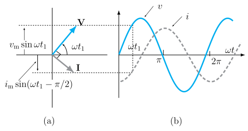
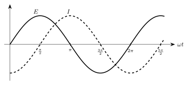
Start your 14-day free trial to unlock the full solution →An inductor behaves as a short circuit to DC (steady state) and as an open circuit to very high frequency AC. In an ideal inductor with AC, the current lags the voltage by (or radians), meaning the voltage peaks a quarter-cycle before the current.
Why This Happens — The Core Idea
An inductor resists changes in current. Its defining equation is — the voltage across it is proportional to how fast the current is changing, not to the current itself.
- For DC, once the current becomes steady, , so . The inductor looks like a plain wire (zero resistance in the ideal case).
- For AC, the current is constantly changing. The faster it changes (higher frequency), the larger the opposing voltage the inductor generates. At very high frequencies, the inductor almost completely blocks the current.
This opposition to change is what creates the phase shift: because voltage depends on the rate of change of current, the voltage reaches its peak when the current is changing fastest — which is when the current itself is passing through zero.
(a) Behaviour with DC and High-Frequency AC
1. Inductor connected to a DC source
When you first connect a DC source (say a battery) to an ideal inductor, the current does not jump instantly to . Instead, it rises gradually:
In steady state (after a long time), the current becomes constant. Since , the voltage across the inductor drops to zero:
In DC steady state, an ideal inductor acts as a short circuit (zero voltage drop, any current can flow).
2. Inductor connected to a high-frequency AC source
For an AC source , the inductive reactance is:
The current amplitude is .
As frequency increases, increases proportionally. At very high frequencies (), , so the current amplitude .
A common mistake is to think an inductor "blocks" DC. It does not — it only resists the change when DC is first applied. In steady state, DC flows freely. It's high-frequency AC that the inductor blocks.
| Condition | Inductor behaves like |
|---|---|
| DC steady state | Short circuit () |
| High-frequency AC | Open circuit () |
| Low-frequency AC | Small resistance-like opposition |
(b) Phase Relation in an Ideal Inductor with AC
3. Setting up the equations
Let the AC source voltage be:
For an ideal inductor, . So:
4. Solving for the current
Integrate both sides:
The constant is zero for steady-state AC (no DC offset). So:
Using and :
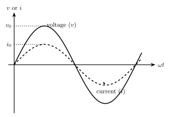
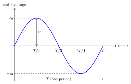
5. Interpreting the phase shift …
Unlock everything free for 14 days
- Full step-by-step solutions
- Concept-first explanations
- Methods, shortcuts & mistakes
- PYQ mapping + timed mock tests
Full access for 14 days. No credit card required.