Physics · Ch 3 — Current Electricity
Kirchhoff's Rules
Kirchhoff's Rules
Why Kirchhoff’s Rules Are Needed
Simple series and parallel resistor formulas are not enough for many circuits. When resistors and cells are interconnected in a complicated way, we need two general rules — Kirchhoff’s junction rule and Kirchhoff’s loop rule — to find all currents and potential differences.
Labelling Currents and Voltages
Before applying the rules, label each resistor with a current symbol (e.g., ) and an arrow showing the assumed direction. If the calculated is positive, the actual current flows along the arrow; if negative, it flows opposite.
For a cell of emf and internal resistance , label its positive terminal and negative terminal . If the current flows from to through the cell, the potential difference is:
If the current is labelled from to , then:
Kirchhoff’s Junction Rule (First Rule)
Statement: At any junction, the sum of currents entering the junction equals the sum of currents leaving the junction.
Why it holds: In steady current, no charge accumulates at any point. The rate of charge flow into a junction must equal the rate of flow out.
Example: In Fig. 3.15, at junction , current enters while and leave. The rule gives:
Kirchhoff’s Loop Rule (Second Rule)
Statement: The algebraic sum of changes in electric potential around any closed loop is zero.
Why it holds: Electric potential depends only on position. Starting from any point and returning to it after going around a closed loop, the net change in potential must be zero.
How to apply: Choose a direction around the loop. For each resistor, the potential drop is (negative if the loop direction matches the current arrow, positive if opposite). For each cell, add if going from negative to positive terminal, and if going from positive to negative. Also include the internal resistance drop with appropriate sign.
Example from Fig. 3.15: For loop ahdcba:
For loop ahdefga:
Worked Example: Cubical Network (Example 3.5)
A battery (negligible internal resistance) is connected across opposite corners of a cube made of 12 resistors, each .
Step 1 – Use symmetry: Paths , , are symmetric, so each carries the same current . At corners , , , the incoming current splits equally into two branches.
Step 2 – Write currents in all edges using the junction rule and symmetry.
Step 3 – Apply loop rule to a closed loop, e.g., :
where and .
Step 4 – Solve for in terms of and :
Step 5 – Equivalent resistance :
For , .
Step 6 – Total current:
Each edge current can now be read from the labelled diagram.
Worked Example: General Network (Example 3.6)
Determine currents in each branch of the network shown in Fig. 3.17.
Step 1 – Assign unknown currents using the junction rule to reduce unknowns. Here, three unknowns , , remain.
Step 2 – Apply loop rule to three independent closed loops.
- Loop ADCA:
Simplifies to:
- Loop ABCA: …
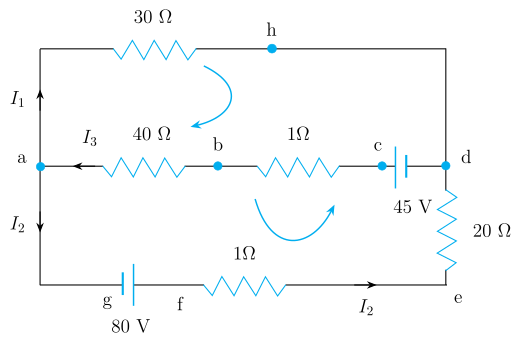
Drawn by us to help you understand the concept clearly, and verified to make sure it's accurate. For exams, practice from your textbook's own diagram.
The figure shows a two-mesh rectangular circuit with labelled nodes and components. The top edge runs from node a (left) to node h (right) through a 30 Ω resistor. The left side has current I₁ flowing upward. A middle horizontal branch goes a → b → c → d: a 40 Ω resistor (a→b), a 1 Ω resistor (b→c), and a 45 V cell (c→d). The right edge has a 20 Ω resistor from d down to e, carrying current I₂. The bottom edge runs g → f → e: an 80 V cell near g and a 1 Ω resistor (f→e). All nodes a, b, c, d, e, f, g, h are labelled, and branch currents I₁, I₂, I₃ are shown with arrows. Two curved arrows inside the mesh windows indicate the chosen loop-traversal directions.
The physical idea taught is Kirchhoff’s rules:
- Junction rule: At any junction, the sum of currents entering equals the sum of currents leaving. At node a, current I₃ enters, while I₁ and I₂ leave, so
At node h, current I₁ enters and only one current leaves, so that leaving current is also I₁.
- Loop rule: The algebraic sum of potential changes around any closed loop is zero.
Using these rules, the textbook derives two loop equations:
- For loop ahdcba (going a→h→d→c→b→a):
Here, –30I₁ is the drop across the 30 Ω resistor (current I₁), –41I₃ is the drop across the 40 Ω and 1 Ω resistors in series (total 41 Ω, current I₃), and +45 is the rise from the 45 V cell (positive terminal encountered first in the chosen direction).
- For loop ahdefga (going a→h→d→e→f→g→a): …