Physics · Ch 2 — Electrostatic Potential and Capacitance
Capacitors in Series
Capacitors in Series
Why Capacitors in Series Share the Same Charge
When capacitors are connected in series, the key physical constraint is that the charge on each capacitor is identical. This is not an assumption — it follows from charge conservation and the fact that the connecting wires between capacitors are conductors.
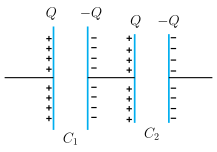
Consider two capacitors and in series. The left plate of is connected to the positive terminal of a battery and acquires charge . The right plate of is connected to the negative terminal and acquires charge .
Now look at the isolated section consisting of the right plate of , the connecting wire, and the left plate of . This entire section is electrically isolated (no connection to the battery). Initially, it is neutral. By conservation of charge, the net charge on this section must remain zero.
If the right plate of had charge and the left plate of had charge , the net charge on the isolated section would be . Any other distribution would create a non-zero net charge, producing an electric field in the conductor. That field would cause charge to flow until neutrality is restored.
Thus, in a series combination:
- Each capacitor has the same magnitude of charge on its plates.
- The polarity alternates: on one plate, on the other.
Voltage Adds in Series
The total potential difference across the series combination is the sum of the individual potential differences across each capacitor:
For a capacitor, . Therefore, for two capacitors:
Factor out :
Effective (Equivalent) Capacitance
We define the effective capacitance of the combination as the capacitance of a single capacitor that would have the same charge and the same total voltage :
Substitute from Eq. (2.56):
Cancel (provided ):
Generalization to Capacitors …
Drawn by us to help you understand the concept clearly, and verified to make sure it's accurate. For exams, practice from your textbook's own diagram.
What the figure shows
The diagram presents two parallel-plate capacitors, labelled C₁ (left) and C₂ (right), placed side by side in a horizontal line. Each capacitor is drawn as a pair of vertical plates: the left plate of each capacitor is marked with a column of + signs, and the right plate with a column of − signs. Above the left plate of C₁ is the label Q, and above its right plate is −Q; similarly, above the left plate of C₂ is Q and above its right plate is −Q. A short connecting wire joins the right plate of C₁ to the left plate of C₂. Two external terminals are shown: one attached to the left plate of C₁ and the other to the right plate of C₂. The labels C₁ and C₂ appear below their respective capacitors.
The physical idea
The figure illustrates the series combination of two capacitors. The key insight is that when capacitors are connected in series, the charge on each capacitor is the same (magnitude ). This happens because the connecting wire between C₁ and C₂ is initially neutral; if the charges on the inner plates were not equal and opposite, an electric field would exist in the wire, causing charge to flow until the net charge on each capacitor becomes zero. Consequently, the left plate of C₁ and the right plate of C₂ each carry and respectively, while the right plate of C₁ and the left plate of C₂ carry and respectively.
The total potential difference across the combination is the sum of the individual potential drops:
where and .
Key formula derived from the figure
Using the above relations, the textbook obtains:
The effective capacitance of the series combination is defined by . Substituting gives:
For capacitors in series, this generalises to:
…
Drawn by us to help you understand the concept clearly, and verified to make sure it's accurate. For exams, practice from your textbook's own diagram.
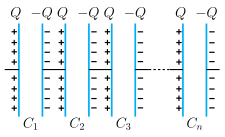
Figure 2.27 shows a series combination of capacitors. The diagram is a horizontal row of four parallel-plate capacitors labelled , , , and from left to right. Each capacitor is drawn as a pair of vertical plates: the left plate has a charge and the right plate has a charge. The capacitors are connected end-to-end by wires, so that the right plate of one capacitor is directly wired to the left plate of the next. Between and , a short dashed/broken wire segment indicates that many intermediate capacitors (the "…" up to ) have been omitted for clarity.
Physical idea: In a series combination, the same charge appears on every plate. The left plate of gets from the battery, and the right plate of gets . Because the connecting wires are conductors, charge redistributes until the net charge on each capacitor is zero — this forces the right plate of to have and the left plate of to have , and so on. Thus, each capacitor stores the same magnitude of charge , but the potential difference across each is different (since ).
Key formula derived from this figure: The total potential drop across the series combination is the sum of the individual drops:
The combination behaves like a single effective capacitor with charge and potential difference , so its effective capacitance satisfies . Substituting gives:
Cancelling (which is non-zero) yields the series capacitance formula:
Here: …