Physics · Ch 9 — Mechanical Properties of Fluids
Streamline Flow
Streamline Flow
Streamline Flow
Fluids in motion can behave in strikingly different ways. Pour honey from a jar — it flows smoothly, in a steady, predictable stream. Turn on a tap fully and watch the water break into a chaotic, splashing jet. The first is an example of streamline flow (also called laminar flow); the second is turbulent flow. Understanding the difference between these two regimes is the foundation of fluid dynamics.
In streamline flow, every particle of the fluid follows a smooth path, and the paths of different particles do not cross each other. At any given point in the fluid, the velocity of every particle that passes through that point is the same — both in magnitude and direction. This means the velocity field is steady in time, though it may vary from one point to another in space.
The word "streamline" itself gives the picture: imagine a steady current in a river where leaves float along fixed, non-intersecting curves. Those curves are streamlines.
A streamline is defined as the curve whose tangent at any point gives the direction of the fluid velocity at that point. Since the velocity at a point is unique at any instant, streamlines can never intersect. If they did, a particle arriving at the intersection would have two possible directions — which is impossible for a steady flow.
The volume of fluid flowing per unit time across any section of a tube of flow is called the volume flow rate or discharge. For a fluid moving with speed through a cross-sectional area , the volume flowing per second is
where has dimensions of and SI units of .
The Equation of Continuity
Consider a fluid flowing steadily through a pipe of varying cross-section. Because the flow is steady, the mass of fluid entering one end of the pipe in a given time must equal the mass leaving the other end — no fluid is created or destroyed inside. This is the principle of conservation of mass applied to a flowing fluid.
Take two cross-sections of the pipe with areas and . Let the fluid speeds at these sections be and , and let the fluid density be (assumed uniform for now). In a small time interval , the mass entering through is
The mass leaving through in the same time is
Conservation of mass demands , so
Cancelling and gives the equation of continuity for an incompressible fluid:
This is one of the most important results in fluid dynamics. It tells us that where the pipe is narrower (smaller ), the fluid must flow faster (larger ) to pass the same volume per second. Where the pipe widens, the flow slows down.
The equation assumes the fluid is incompressible (density constant). For gases, where density can change significantly, the full form must be used. In this chapter, unless stated otherwise, we treat liquids as incompressible.
Volume Flow Rate and Mass Flow Rate
The product is the volume flow rate (discharge) . Its SI unit is . The mass flow rate is , with SI unit .
For an incompressible fluid in steady flow, the volume flow rate is the same at every cross-section of a tube of flow. This is a direct consequence of the equation of continuity. …
Drawn by us to help you understand the concept clearly, and verified to make sure it's accurate. For exams, practice from your textbook's own diagram.
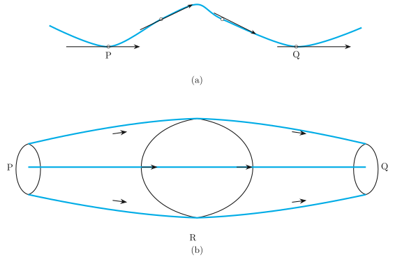
Figure 9.7 in the NCERT textbook is a two-part diagram that builds the visual language for streamline flow — the foundation on which Bernoulli’s principle rests.
Panel (a) shows a single, smooth curve running from point P to point Q. This curve is the trajectory of one fluid particle. At several points along this path, small arrows are drawn tangent to the curve. Each arrow represents the instantaneous velocity vector of that particle at that location. The key idea: in streamline flow, the velocity at any fixed point in space is constant in time, so the path of any particle passing through that point is the same curve. The tangent arrows make this explicit — the direction of flow at each point is exactly the direction of the curve itself.
Panel (b) expands the picture. Instead of one particle’s path, you see a bundle of such curves — a family of streamlines — all originating from the same upstream region P. The bundle passes through a cross-sectional plane labelled R, then spreads out again toward Q. Arrows along the bundle indicate the direction of flow. This panel teaches the concept of a streamtube: the volume bounded by a set of streamlines. Because no fluid crosses a streamline, the mass flow rate through any cross-section of the tube is constant. That is the physical content of the equation of continuity, which the textbook derives using this figure.
Here and are the cross-sectional areas at two different points along the streamtube, and , are the corresponding flow speeds. The product is the volume flow rate (assuming constant density). The formula says: where the tube narrows, the speed must increase; where it widens, the speed decreases. This is a direct consequence of mass conservation for an incompressible fluid.
The same figure then leads to Bernoulli’s equation. Applying the work-energy theorem to a small element of fluid moving along a streamline from one cross-section to another gives:
Here is the pressure, the density, the speed, the acceleration due to gravity, and the height above a reference level. The subscripts 1 and 2 refer to two points on the same streamline. The equation states that the sum of pressure energy, kinetic energy per unit volume, and gravitational potential energy per unit volume remains constant along a streamline in steady, incompressible, non-viscous flow.
Bernoulli’s equation applies only along a single streamline — you cannot mix values from different streamlines unless the flow is irrotational. Also, it assumes no viscosity and steady flow. In real fluids, energy is lost to viscous dissipation, so the equation is an idealisation. …
Drawn by us to help you understand the concept clearly, and verified to make sure it's accurate. For exams, practice from your textbook's own diagram.
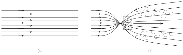
Figure 9.8 in the NCERT textbook is a two-part illustration that contrasts the two fundamental regimes of fluid motion: streamline (laminar) flow and turbulent flow. The figure does not have labelled axes or a coordinate grid; it is a schematic drawing meant to show the pattern of fluid motion, not a quantitative plot.
Panel (a) shows several parallel, horizontal streamlines with arrowheads pointing to the right. These lines are smooth, evenly spaced, and do not cross each other. This is the visual signature of laminar flow: every fluid particle follows a well-defined path, and adjacent layers of fluid slide past one another without mixing. The arrowheads indicate the direction of flow. In this regime, the fluid velocity at any fixed point in space is constant in both magnitude and direction over time. The key physical idea is that the flow is orderly and predictable — you can trace the trajectory of any particle without ambiguity.
Panel (b) depicts a jet of fluid (air, in the caption’s example) moving horizontally from left to right and striking a vertical flat plate placed perpendicular to the flow. The streamlines approach the plate from the left, but instead of passing smoothly around it, they curl into loops — eddies and whirlpools — both above and below the plate. The lines are no longer parallel; they cross, loop back, and form chaotic patterns. This is turbulent flow: the velocity at a fixed point fluctuates randomly in both magnitude and direction, and the fluid mixes vigorously. The physical lesson is that when an obstacle disrupts a smooth flow, the orderly laminar regime can break down into a disordered, energy-dissipating turbulent one.
The transition from laminar to turbulent flow is not abrupt. It depends on a dimensionless quantity called the Reynolds number (), which compares inertial forces to viscous forces. For flow in a pipe, typically gives laminar flow, while gives turbulent flow.
The textbook develops Bernoulli’s principle alongside this figure, and the principle applies strictly to streamline (laminar) flow of an incompressible, non-viscous fluid. The central result is:
Here:
- is the static pressure of the fluid at a given point (force per unit area exerted by the fluid on its surroundings).
- is the density of the fluid (mass per unit volume).
- is the flow speed of the fluid at that point.
- is the acceleration due to gravity.
- is the height of the point above a reference level (the gravitational potential energy per unit mass).
The equation says that along a streamline in steady, ideal flow, the sum of pressure energy, kinetic energy per unit volume, and gravitational potential energy per unit volume remains constant. This is a statement of energy conservation for a fluid element moving along a streamline. …