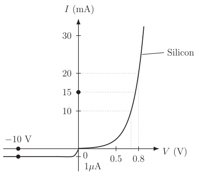
Q.The V-I characteristic of a silicon diode is shown in Fig. 14.17. Calculate the resistance of the diode at
You're viewing a preview — the full solution, concept, methods & PYQ mapping are locked.
Start your 14-day free trial to unlock the full solution →The resistance of a diode is found from the slope of its V-I characteristic at the given operating point. For the forward bias case at , we use the linear region between two known points to get . For the reverse bias case at , the nearly flat curve gives a very high resistance .
The key idea is that a diode does not have a single, fixed resistance. Its resistance depends on where you are on the V-I curve. In forward bias, the diode conducts heavily and the resistance is small. In reverse bias, almost no current flows, so the resistance is enormous.
We calculate the resistance differently depending on whether we want the static (DC) resistance or the dynamic (AC) resistance. The problem asks for "the resistance of the diode" at a given current or voltage. From the graph, we can extract the necessary values.
1. Forward bias case:
The forward characteristic is steep and approximately linear between the marked points. This means we can treat it as a straight line in that region.
The two given points on the forward branch are:
- Point A: ,
- Point B: ,
Since the curve is nearly a straight line through these points, the dynamic resistance (the slope resistance at any point between them) is constant. This is the resistance that matters for small signal changes around the operating point.
Dynamic resistance
Using the two points:
Therefore:
Notice that we didn't need to find the exact voltage at because the slope is constant. The dynamic resistance is the same for any current between 10 mA and 20 mA on this linear segment.
A common mistake is to compute the static resistance at . That would require reading from the graph, giving . But the problem asks for the resistance of the diode, which in the context of a V-I characteristic usually means the dynamic (slope) resistance unless specified otherwise. The static resistance is much larger and not what is intended here.
2. Reverse bias case: …
Unlock everything free for 14 days
- Full step-by-step solutions
- Concept-first explanations
- Methods, shortcuts & mistakes
- PYQ mapping + timed mock tests
Full access for 14 days. No credit card required.