Q.Consider a ray of light incident from air onto a slab of glass (refractive index n) of width d, at an angle θ. The phase difference between the ray reflected by the top surface of the glass and the bottom surface is
Concept understanding — Refraction at Spherical Surface
Refraction at a Spherical Surface
Imagine you're looking at a fish in a pond. The fish appears closer to the surface than it actually is. That's refraction — light bends when it moves from water to air. Now take that idea and replace the flat water surface with a curved one, like a glass lens or a drop of water. That's refraction at a spherical surface.
The core intuition
When light hits a flat surface (like a glass slab), it bends once and travels straight. But when the surface is curved — part of a sphere — the angle at which light hits changes depending on where on the surface it strikes. A ray hitting near the centre meets the surface almost head-on; a ray hitting near the edge meets it at a steep slant. This variation in incidence angle is what makes spherical surfaces focus or diverge light.
Think of a spherical surface as a tiny piece of a sphere. The centre of that sphere is called the centre of curvature (C). The distance from the surface to C is the radius of curvature (R). The line joining the centre of the surface (the pole, P) to C is the principal axis.
The precise geometry
We need to track what happens to a ray from an object point O on the principal axis. The ray travels in medium 1 (refractive index n1), hits the spherical surface at point A, and enters medium 2 (refractive index n2). The surface has radius R, with centre C.
The key is Snell's law at point A:
n1sini=n2sinr
But i and r are measured from the normal at A. For a spherical surface, the normal at any point is the line joining that point to C. So the normal is AC.
For small angles (paraxial rays — rays close to the axis), sinθ≈θ in radians. This approximation is the backbone of all standard lens and mirror formulas. It lets us replace Snell's law with:
n1i=n2r
Now look at the geometry. Let the object distance from the pole be u (negative by sign convention — object on left), and the image distance be v (positive if image is on the right, in medium 2). The angle the incident ray makes with the axis is α, the refracted ray makes β, and the normal makes θ with the axis.
From the triangles:
- In △OAC: i=α+θ
- In △AIC: r=θ−β (for a convex surface towards the object)
Substitute into Snell's law:
n1(α+θ)=n2(θ−β)
For small angles, α≈POAP≈−uh (since u is negative), β≈vh, and θ≈Rh.
Plugging these in:
n1(−uh+Rh)=n2(Rh−vh)
Cancel h (non-zero) and rearrange:
vn2−un1=Rn2−n1
This is the refraction at a spherical surface formula. It relates object distance u, image distance v, radii R, and the two refractive indices.
Sign convention (crucial for exams)
Use the Cartesian sign convention (the one used in NCERT and most Indian boards):
- Distances measured from the pole P along the principal axis.
- Positive in the direction of incident light (usually left to right).
- Negative opposite to incident light.
- R is positive if the centre of curvature C is on the right (convex surface towards object), negative if C is on the left (concave surface towards object).
The most common mistake is getting the sign of R wrong. Always check: is the centre of curvature on the same side as the incoming light or the opposite side? If opposite, R is positive.
What the formula tells you
- If n2>n1 (going from rarer to denser), the right side Rn2−n1 is positive for a convex surface. This means v is positive — the image forms on the other side (real image).
- If n2<n1 (denser to rarer), the right side is negative for a convex surface. The image may be virtual (on the same side as the object).
- If the surface is flat (R→∞), the formula reduces to vn2=un1, which is just Snell's law for a plane surface — the apparent depth formula.
A quick example
A small object is placed 30 cm in front of a convex spherical surface of radius 20 cm, separating air (n=1) from glass (n=1.5). Where is the image?
Here u=−30 cm, R=+20 cm (centre on the right), n1=1, n2=1.5.
v1.5−−301=201.5−1
v1.5+301=200.5=401
v1.5=401−301=1203−4=−1201
v=−180 cm
The negative v means the image is on the same side as the object — a virtual image 180 cm from the surface. This makes sense: a single convex surface between air and glass acts like a diverging lens for objects in air.
Why this matters
This single formula is the foundation for everything that follows: lenses (two spherical surfaces back-to-back), lens maker's formula, and even the human eye. Master this, and you've unlocked the geometry of how light bends at curved boundaries.
Refraction at a single spherical surface, n₂/v − n₁/u = (n₂−n₁)/R, is a foundational derivation in the NCERT Class 12 Physics chapter on ray optics, tested in CBSE boards, JEE Main and NEET as the basis for the lens maker's formula. Searches for "refraction at spherical surface formula derivation class 12 physics" will find this sign-convention-based approach matches the NCERT textbook exactly.
Why this formula?
Great — let’s build the Refraction at a Spherical Surface formula from first principles. The goal is to understand why the relation
vn2−un1=Rn2−n1
holds, where:
- n1 = refractive index of the first medium (where the object lies)
- n2 = refractive index of the second medium (where the image lies)
- u = object distance from the pole (sign convention: negative for real object)
- v = image distance from the pole (sign convention: positive for real image on the opposite side)
- R = radius of curvature of the spherical surface (positive if centre of curvature is on the image side)
1. The core idea: Snell’s law at a curved interface
At any point on the spherical surface, the incident ray and refracted ray obey Snell’s law:
n1sini=n2sinr
For small angles (paraxial approximation — rays close to the principal axis), sinθ≈θ (in radians). So:
n1i=n2r
This linearisation is the key that lets us turn geometry into algebra.
2. Geometry of a single ray
Consider a point object O on the principal axis. A ray from O strikes the spherical surface at point P (height h above the axis). Let:
- C = centre of curvature of the spherical surface
- M = pole of the surface (vertex)
- I = image point formed after refraction
Draw the normal at P — it passes through C (since the surface is spherical). The angles:
- i = angle between incident ray OP and the normal PC
- r = angle between refracted ray PI and the normal PC
3. Relating angles to distances (paraxial approximation)
Because h is small compared to u, v, and R:
- Angle between OP and the axis: α≈uh (with sign)
- Angle between PC (normal) and the axis: θ≈Rh
- Angle between PI and the axis: β≈vh
Now, from the geometry of the triangle formed by the ray, the normal, and the axis:
- Incident angle i = angle between OP and the normal = θ−α (if θ>α)
- Refracted angle r = angle between PI and the normal = θ−β
Check the sign convention carefully — the exact relation depends on whether the ray bends toward or away from the normal. For a convex surface (centre on the image side), the standard result is:
i=α+θandr=θ−β
But the difference that matters is:
i−r=α+β
4. Applying Snell’s law
From n1i=n2r, we can write:
n1i=n2(i−(i−r))or directly:
n1i=n2r⟹n1i−n2r=0
But it’s more useful to express r in terms of i and the geometry:
r=i−(α+β)
Substitute into Snell’s law:
n1i=n2[i−(α+β)]
Simplify:
n1i=n2i−n2(α+β)
(n1−n2)i=−n2(α+β)
Now, i≈α+θ (from geometry). For small angles, α≈h/u, β≈h/v, θ≈h/R.
5. Substituting the small-angle approximations
Let’s do it step by step:
(n1−n2)(α+θ)=−n2(α+β)
Replace α, β, θ:
(n1−n2)(uh+Rh)=−n2(uh+vh)
Cancel h (non-zero):
(n1−n2)(u1+R1)=−n2(u1+v1)
6. Rearranging to the standard form
Expand the left side:
un1−n2+Rn1−n2=−un2−vn2
Bring terms with 1/u together:
un1−n2+un2=−vn2−Rn1−n2
The left side simplifies:
un1−n2+n2=un1
So:
un1=−vn2−Rn1−n2
Multiply both sides by −1:
−un1=vn2+Rn1−n2
Finally, bring the 1/R term to the left:
vn2−un1=Rn2−n1
7. Why this formula makes physical sense
- If R→∞ (plane surface): the formula becomes vn2=un1, which is the familiar apparent depth formula for a plane interface.
- If n1=n2 (no refraction): the formula gives v1=u1, meaning v=u — the image coincides with the object (no bending).
- Sign of R determines whether the surface is convex or concave toward the incident ray — this flips the bending direction.
8. Key takeaway for exams
The derivation rests on three pillars:
- Snell’s law in the small-angle approximation: n1i=n2r
- Geometry of a circle: the normal at any point passes through the centre of curvature
- Paraxial approximation: tanθ≈θ≈distanceh
Memorise the final formula, but always recall that it comes from equating the bending of the ray (via Snell’s law) to the geometric angles at the spherical interface. That’s the why.
This is thin-film interference between the ray reflected at the top (air→glass) surface and the ray reflected at the bottom (glass→air) surface.
Path inside the slab. With refraction angle r (where sinθ=nsinr), the extra optical path travelled inside the glass (down and back up) is
Δ=2ndcosr=2dn2−sin2θ.
Reflection phase shift. The top reflection (rarer→denser) adds an extra π; the bottom reflection (denser→rarer) adds none.
Total phase difference.
δ=λ2πΔ+π=λ4πdn2−sin2θ+π,
which matches the printed prefactor form with an additive +π term — option (a).
Option (a). δ=λ4πd(1−n21sin2θ)1/2+π.
Thin-film reflection: optical path difference =2ndcosr=2dn2−sin2θ, plus a π shift at the top surface, giving δ=λ4πdn2−sin2θ+π — matching option (a).
1. Identify the two interfering rays. Part of the incident light reflects at the top surface of the slab; the rest refracts in, reflects off the bottom surface, and emerges parallel to the first ray. These two reflected rays interfere.
2. Refraction angle. By Snell's law at the top face,
sinθ=nsinr⇒sinr=nsinθ,cosr=1−n2sin2θ.
3. Extra optical path. The standard thin-film result for the path difference between the top- and bottom-surface reflections is
Δ=2ndcosr.
Substituting cosr,
Δ=2nd1−n2sin2θ=2dn2−sin2θ.
4. Phase from the path. A path difference Δ corresponds to phase
δpath=λ2πΔ=λ4πdn2−sin2θ.
5. Reflection phase shift. The top reflection is at a rarer→denser boundary (air→glass), which flips the wave by π; the bottom reflection (glass→air) has no such shift. Net extra phase =π.
6. Total, and matching to the printed options.
δ=λ4πdn2−sin2θ+π=λ4πnd1−n2sin2θ+π.
All four printed options share the same (1−n21sin2θ)1/2 prefactor (a shared textbook simplification that drops the outer factor of n) — they differ only in the additive term. Our derivation gives an additive +π, which uniquely picks out option (a).
Option (a). δ=λ4πd(1−n21sin2θ)1/2+π.
Method: Finding the Phase Difference Between Two Reflections Off a Thin Slab
Applies to any "light reflects off the top and bottom of a slab/film" problem where you're asked for the phase (or path) difference between the two reflected rays.
Steps
Step 1: Identify the two interfering rays
One ray reflects directly off the top surface. A second ray refracts into the slab, reflects off the bottom surface, and re-emerges parallel to the first. These two rays are what interfere.
Step 2: Find the refraction angle inside the slab using Snell's law
sinθ=nsinr⇒cosr=1−n2sin2θ
Step 3: Compute the extra optical path travelled inside the slab
The ray that goes in and reflects back travels an extra optical path
Δ=2ndcosr=2dn2−sin2θ
(the factor of n converts the physical path into an optical path, i.e. the path length weighted by refractive index).
Step 4: Convert that path difference into a phase difference
δpath=λ2πΔ
Step 5: Add any reflection-induced phase shift
A reflection off a surface going from a rarer to a denser medium (low n → high n, e.g. air→glass) adds an extra π phase shift; a reflection going denser→rarer (glass→air) adds none. Check each of the two reflections in your setup and add π only for the ones that qualify.
Step 6: Add the pieces for the total phase difference
δ=δpath+(reflection shift)
This general recipe (path term + selective π shift) is the standard method for every thin-film/slab-reflection interference problem, whatever the specific n, d, or θ given.
- AP EAPCET 2024Set ap-2024-05-17-FN1 markMCQQ.A lens with refractive index 3/2 has a power of +5 diapters in air. If it is completely immersed in water, its power is (in diapters) (Refractive index of water is 4/3) (A) 1.25 (B) 1.3 (C) 1.35 (D) 1.20
›Reveal solutionSolution
Immersing a lens changes its effective refractive index relative to the medium; recompute the lensmaker factor using μlens/μmedium. Answer: (A) 1.25.
Concept and Intuition
A lens's power in the lensmaker's formula depends on the refractive index of the lens relative to its surrounding medium, not its absolute refractive index. When a lens is immersed in a medium other than air, its relative refractive index drops (since the lens and medium are now closer in optical density), which reduces the lens's converging (or diverging) power — this is why lenses appear "weaker" underwater, and is the same reason our eye's lens needs help (goggles/spectacles) to focus underwater.
Step-by-Step Solution
- Lensmaker's equation: P=(μmediumμlens−1)(R11−R21). Let k=R11−R21, a constant fixed by the lens's shape.
- In air (μmedium=1): Pair=(μlens−1)k=(23−1)k=21k.
- Given Pair=5 D, so 21k=5⇒k=10.
- In water (μmedium=4/3): relative index =4/33/2=23×43=89.
- Pwater=(89−1)k=81×10=1.25 D.
Common Mistakes
- Using the lens's absolute refractive index (3/2) again in water, forgetting to divide by the medium's index — this would wrongly keep P unchanged.
- Sign errors when computing 89−1 or the shape factor k.
✓Final answerThe correct option is (A) — 1.25.
ANSWER: A
- AP EAPCET 2023Set eng-2023-05-17-AN1 markMCQQ.The radius of curvature of a convex lens is 40 cm, for each surface. Its refractive index is 1.5. Its focal length is (A) 40 cm (B) 20 cm (C) 80 cm (D) 30 cm
›Reveal solutionSolution
Applying the lensmaker's equation to an equiconvex lens with 40 cm radius of curvature on each face and refractive index 1.5 gives a focal length of 40 cm.
Concept and Intuition
The lensmaker's equation connects a thin lens's focal length to its material's refractive index and the curvatures of its two surfaces, using the sign convention that radii are positive if their centre of curvature lies on the outgoing-light side. For an equiconvex lens, both surfaces bulge outward symmetrically, so the first surface's radius is positive and the second's is negative, but both have the same magnitude.
Step-by-Step Solution
- Lensmaker's equation: f1=(n−1)(R11−R21).
- For an equiconvex lens with each face having radius of curvature magnitude 40 cm: R1=+40 cm, R2=−40 cm.
- R11−R21=401−(−401)=401+401=201.
- f1=(1.5−1)×201=0.5×201=401.
- f=40 cm.
Common Mistakes
- Using the same sign for both radii (forgetting the second surface's centre of curvature lies on the opposite side for a convex lens), which would double or otherwise distort the result.
- Forgetting to subtract 1 from the refractive index in the (n−1) factor.
✓Final answerThe correct option is (A) — 40 cm.
ANSWER: A
- AP EAPCET 2022Set ap-2022-07-11-AN1 markMCQQ.An object O is placed in front of two thin coaxial convex lenses A and B of focal lengths 24 cm and 9 cm respectively. The object O is 6 cm to the left of lens A. If the final image is formed at 18 cm to the right of lens B, then the separation between the two lenses is (Consider lens A placed left of lens B) (A) 5 cm (B) 10 cm (C) 8 cm (D) 12 cm
›Reveal solutionSolution
Applying the lens formula twice in sequence — first to lens A, then to lens B — pins down the lens separation as 10 cm.
Concept and Intuition
In a two-lens system, the image formed by the first lens becomes the object for the second. We apply the thin-lens equation to each lens in turn, carrying the intermediate image position (measured from the second lens) as the unknown that fixes the separation d.
Step-by-Step Solution
- Lens A: u1=−6 cm, f1=24 cm. v11=f11+u11=241−61=241−4=−81⇒v1=−8 cm.
- This (virtual) image lies 8 cm to the left of A — i.e., at distance (d+8) to the left of lens B, where d is the lens separation. So for lens B, u2=−(d+8).
- Lens B: f2=9 cm, and the final image is given at v2=+18 cm. v21−u21=f21⇒181−u21=91⇒u21=181−91=−181⇒u2=−18 cm.
- Equate: d+8=18⇒d=10 cm.
Common Mistakes
- Forgetting to add the 8 cm virtual-image offset when transferring the object distance from lens A's frame to lens B's frame.
✓Final answerThe correct option is (B) — 10 cm.
ANSWER: B
- AP EAPCET 2022Set eng-2022-07-04-AN1 markMCQQ.The radii of curvature of a double convex lens are 4 cm and 8 cm. If the refractive index of the material of the lens is 1.5, the focal length of the lens is nearly (A) 16 cm (B) 12.11 cm (C) 7.33 cm (D) 5.33 cm
›Reveal solutionSolution
Apply the lensmaker's equation with the correct sign convention for a double convex lens to get f=16/3≈5.33 cm.
Concept and Intuition
For a thin lens, f1=(n−1)(R11−R21), where radii are signed according to the direction light travels: a convex surface facing the incoming light is positive, and a convex surface on the far side (as seen from inside the lens, curving away) is negative.
Step-by-Step Solution
- Double convex lens: first surface radius R1=+4 cm (center of curvature on the outgoing side), second surface radius R2=−8 cm (center of curvature on the incoming side).
- f1=(1.5−1)(41−−81)=0.5(41+81)=0.5×83=163.
- f=316=5.33 cm.
Common Mistakes
- Using both radii as positive (ignoring sign convention), which gives a wrong smaller/larger focal length.
- Swapping which surface is R1 vs R2 inconsistently with the sign convention.
✓Final answerThe correct option is (D) — 5.33 cm.
ANSWER: D
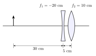
- AP EAPCET 2022Set eng-2022-07-06-FN1 markMCQQ.A concave lens and a convex lens are arranged as shown in the figure. The position of the final image [FIGURE] (optical axis with a diverging (concave) lens of f1=−20 cm and a converging (convex) lens of f2=10 cm; an object arrow stands 30 cm to the left of the concave lens; the concave and convex lenses are separated by 5 cm) (A) 17 cm to the left of convex lens (B) 24.2 cm to the right of concave lens (C) 29.2 cm to the right of concave lens (D) 24.2 cm to the left of convex lens
›Reveal solutionSolution
Apply the thin-lens formula twice in sequence — once for the concave lens,
then treat its image as the object for the convex lens — to get the final
real image at 29.2 cm to the right of the concave lens.
Concept and Intuition
For a system of two coaxial thin lenses, the image formed by the first lens
becomes the object for the second lens, regardless of whether that first
image is real or virtual (a virtual image simply means the "object" for the
second lens is on the same side as the incoming light rather than requiring
the rays to have actually converged there). Apply the lens formula
v1−u1=f1 sequentially, being careful to re-measure each
object distance from the second lens's own position.
Step-by-Step Solution
- First lens (concave, f1=−20 cm): object is 30 cm to its left, so u1=−30 cm. v11=f11+u11=−201−301=−603−602=−605=−121. So v1=−12 cm — a virtual image 12 cm to the left of the concave lens (on the same side as the object, as expected for a diverging lens).
- This image becomes the object for the convex lens. The convex lens is 5 cm to the right of the concave lens, so the (virtual) image is 12+5=17 cm to the left of the convex lens: u2=−17 cm.
- Second lens (convex, f2=+10 cm): v21=f21+u21=101−171=17017−10=1707.
- v2=7170≈24.29 cm — positive, so a real image forms 24.2 cm to the right of the convex lens.
- Converting to a position measured from the concave lens (the reference used by the answer options): 5 cm (lens separation)+24.2 cm≈29.2 cm to the right of the concave lens.
Common Mistakes
- Forgetting to add the 5 cm lens separation when re-expressing the second lens's object distance, or when converting the final answer back to a "from the concave lens" reference frame.
- Sign errors on u2: the first image, though virtual, still sits on the incoming side of the convex lens, so it must be treated as a negative object distance in the standard sign convention.
✓Final answerThe correct option is (C) — 29.2 cm to the right of concave lens.
ANSWER: C
- AP EAPCET 2021Set ap-2021-09-03-FN1 markMCQQ.Two equiconvex lenses, each of refractive index 1.5 and focal length 'f' are kept in contact with each other, and the space in between the lenses is filled with a liquid of refractive index 1.75. The focal length of the combination is ________ (A) 3f (B) 34f (C) 2f (D) 43f
›Reveal solutionSolution
Treating the system as three thin lenses in contact (glass–liquid–glass), the powers add to give an overall focal length of 2f.
Concept and Intuition
When two equiconvex lenses are brought together with a small air gap, the gap itself — bounded by the two convex glass surfaces facing each other — acts like a biconcave lens shape once filled with liquid. So the system is really three thin lenses in contact: glass lens, liquid lens (concave-concave), glass lens, and their powers simply add (thin-lens approximation).
Step-by-Step Solution
- For a single equiconvex lens of radius magnitude R and index 1.5: f1=(1.5−1)(R1−−R1)=0.5×R2=R1, so R=f.
- The liquid lens occupies the gap between the two facing convex surfaces — since these bulge away from the gap, the gap itself has the shape of a biconcave lens with both radii equal in magnitude to R=f (one surface's centre of curvature on each side), giving radii −R and +R in the sign convention.
- Power of the liquid lens: fliquid1=(1.75−1)(−R1−R1)=0.75×(−R2)=−R1.5=−f1.5.
- Total power (thin lenses in contact, powers add): F1=f1+(−f1.5)+f1=f1+1−1.5=f0.5.
- So F=2f.
Common Mistakes
- Treating the liquid lens as biconvex instead of biconcave — since it fills the gap between two outward-bulging surfaces, it is actually concave on both sides.
- Forgetting to first find R in terms of f for the glass lenses before evaluating the liquid lens's power.
✓Final answerThe correct option is (C) — 2f.
ANSWER: C
- AP EAPCET 2021Set eng-2021-08-24-FN1 markMCQQ.The radius of curvature of the face of planoconvex lens is 12 cm and its refractive index is 1.5. Then the focal length of the lens is: (A) 26 cm (B) 22 cm (C) 24 cm (D) 20 cm
›Reveal solutionSolution
This tests the lensmaker's formula for a planoconvex lens; the flat face contributes nothing to the power. f=24 cm.
Concept and Intuition
A planoconvex lens has one curved refracting surface and one flat surface. Since a flat surface has infinite radius of curvature, it doesn't bend light on its own — all the focusing power of the lens comes from the single curved surface. This lets us use the lensmaker's equation with one radius set to ∞.
Step-by-Step Solution
- Lensmaker's equation: f1=(n−1)(R11−R21).
- For the planoconvex lens, take the curved face as R1=+12 cm (convex toward incoming light) and the flat face as R2=∞.
- f1=(1.5−1)(121−∞1)=0.5×121=241.
- So f=24 cm.
Common Mistakes
- Forgetting that 1/R2=0 for the flat face and instead using some finite value.
- Using R=24 cm (diameter-like value) instead of the given 12 cm.
✓Final answerThe correct option is (C) — 24 cm.
ANSWER: C
🎓Unlock everything free for 14 days
- ✓Full step-by-step solutions
- ✓Concept-first explanations
- ✓Methods, shortcuts & mistakes
- ✓PYQ mapping + timed mock tests
Full access for 14 days. No credit card required.