Q.Draw a circuit diagram showing the biasing of a photo-diode and explain its working. Also draw its I-V characteristics.
You're viewing a preview — the full solution, concept, methods & PYQ mapping are locked.
Start your 14-day free trial to unlock the full solution →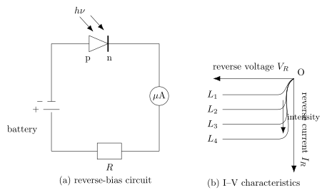
A photodiode is operated reverse-biased so that light-generated carriers dominate the (otherwise tiny) reverse saturation current, making the reverse current a sensitive, nearly linear measure of light intensity.
Circuit / biasing: A photodiode is a p–n junction diode, enclosed so that light can fall on the junction, and it is connected in the circuit with reverse bias: the p-side connected to the negative terminal and the n-side to the positive terminal of the battery, in series with a microammeter/load resistor to measure the photocurrent.
Working: In reverse bias, normally only a very small reverse saturation current flows (due to thermally generated minority carriers). When light of energy (the band-gap energy) falls on the junction, it generates additional electron–hole pairs near the depletion region. The junction's electric field quickly sweeps these photo-generated carriers across the junction, adding to the reverse current. Since more incident photons generate more electron-hole pairs, the reverse photocurrent increases with the intensity of incident light, roughly linearly — this is what makes the photodiode useful as a light-intensity sensor, responding very fast (used for high-speed switching/detection).
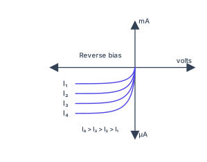
I–V characteristics: The characteristic curves are plotted for reverse voltage on the x-axis and reverse current on the y-axis, for different illumination levels. They show: …
Unlock everything free for 14 days
- Full step-by-step solutions
- Concept-first explanations
- Methods, shortcuts & mistakes
- PYQ mapping + timed mock tests
Full access for 14 days. No credit card required.