Q.Consider Experiment 6.2.
Concept understanding — Electromagnetic Induction
Electromagnetic Induction
Electromagnetic induction is the phenomenon in which a changing magnetic flux through a circuit produces an electromotive force (emf) — and hence a current, if the circuit is closed. It is the single idea behind generators, transformers, inductors, and the entire AC power grid.
The Central Discovery
Michael Faraday found (1831) that a current is induced in a coil not when a magnet sits still near it, but only while the magnet moves — that is, only while the magnetic flux linked with the coil is changing. A steady magnet, however strong, induces nothing.
Magnetic Flux
The key quantity is magnetic flux ΦB through a surface of area A in a field B:
ΦB=B⋅A=BAcosθ
where θ is the angle between B and the area's normal. Its SI unit is the weber (Wb), where 1 Wb=1 T⋅m2.
Flux can change in three distinct ways, and any of them induces an emf:
- the field strength B changes,
- the area A of the loop changes,
- the orientation θ changes (a coil rotating in a field — the basis of the generator).
Faraday's Law
The induced emf equals the negative rate of change of flux. For a coil of N turns:
E=−NdtdΦB
The faster the flux changes, the larger the emf. This is why a magnet dropped quickly through a coil gives a bigger deflection than one moved slowly.
Lenz's Law — the Minus Sign
The negative sign expresses Lenz's law: the induced current flows in the direction that opposes the change producing it. Push a magnet's north pole toward a coil, and the coil's near face becomes a north pole to repel it; pull it away, and the face becomes a south pole to attract it. This is simply energy conservation — you must do work against this opposition, and that work becomes the electrical energy of the induced current.
Motional emf
A special, very useful case: a conducting rod of length l moving with speed v perpendicular to a field B sweeps out area and develops an emf
E=Blv
Here the emf arises because the free charges in the rod experience a magnetic force qv×B, which drives them along the rod.
Induction does not require physical contact or a battery. It is the change of flux that matters, not its value. A loop sitting in a huge but constant field has zero induced emf.
Where It Leads
Once a coil's own changing current induces an emf in itself, we call it self-inductance (L); when one coil's changing current induces emf in a neighbour, that is mutual inductance (M). Both are direct consequences of Faraday's law. Rotate a coil steadily in a magnetic field and the sinusoidal emf it produces is exactly the alternating voltage that runs the AC circuits studied in this chapter.
Faraday's and Lenz's laws of electromagnetic induction form one of the highest-weightage chapters in NCERT Class 12 Physics, tested extensively in CBSE boards, JEE Main and NEET. Anyone searching "Faraday's law of electromagnetic induction formula and examples class 12 physics" will find this changing-flux explanation, including the motional emf case, is exactly how NCERT presents the chapter.
Why this formula?
Electromagnetic Induction
Electromagnetic induction is the effect discovered by Faraday: a changing magnetic flux through a circuit drives an induced EMF (and hence a current). The key word is changing — a steady field, however strong, induces nothing.
Magnetic flux
Flux measures how many field lines thread a surface bounded by the loop:
ΦB=∫B⋅dA=BAcosθ
It can change three ways: by changing B, by changing the area A, or by rotating the loop (changing θ).
Faraday's law
The induced EMF equals the rate of change of flux:
E=−dtdΦB
For a coil of N turns, E=−NdtdΦB. The EMF depends on how fast the flux changes, not on the flux itself — a slow change gives a small EMF, a rapid change a large one.
Lenz's law — the minus sign
The negative sign is Lenz's law: the induced current flows in the direction that opposes the change producing it. Push a magnet's north pole toward a coil and the coil's near face becomes a north pole to repel it; pull it away and the face becomes a south pole to attract it. This opposition is required by energy conservation — you must do work against the induced current, and that work is what becomes electrical energy. If the current instead aided the change, energy would be created from nothing.
A worked idea
A rod of length l slides at speed v along rails in a field B. In time dt it sweeps area lvdt, so the flux changes by dΦB=Blvdt, giving a motional EMF:
E=dtdΦB=Blv
The same result follows from the magnetic force q(v×B) pushing free electrons to one end of the rod — a direct check that Faraday's law and the Lorentz force tell one consistent story.
The key idea is Electromagnetic Induction: a changing magnetic flux through coil C1 induces an EMF in it, and the induced current (and thus the galvanometer deflection) depends on the rate of change of that flux — here the flux is produced by the current-carrying coil C2, not a magnet.
(a) To obtain a large deflection of the galvanometer, one or more of the following:
- Use a rod of soft iron inside coil C2 — this concentrates the field and increases the flux linked with C1.
- Connect C2 to a more powerful battery — a larger current in C2 produces a larger field.
- Move C2 rapidly towards (or away from) C1 — the induced emf depends on the rate of change of flux, so a faster motion gives a bigger deflection.
(b) To demonstrate induced current without a galvanometer: replace the galvanometer with a small bulb (the kind found in a torch light). The relative motion between the two coils causes the bulb to glow momentarily, directly showing the presence of an induced current.
- Use a soft-iron core inside C2, a stronger battery for C2, and/or move C2 rapidly towards/away from C1 — each increases the rate of change of flux linked with C1.
- Replace the galvanometer with a small bulb; it glows briefly whenever the coils are in relative motion, showing the induced current.
This question is about NCERT's Experiment 6.2 — coil C2, carrying a steady current from a battery, is moved relative to a stationary coil C1 that is wired to a galvanometer G (Fig 6.2), not a bar magnet. To get a large deflection: insert a soft-iron rod inside C2, use a more powerful battery for C2, or move C2 faster. Without a galvanometer, a small bulb in place of G will glow whenever the coils are in relative motion.
What Experiment 6.2 actually is
Unlike Experiment 6.1 (a bar magnet moved near a coil), NCERT's Experiment 6.2 uses two coils: coil C2 is connected to a battery (through a tapping key), so it carries a steady current and behaves like an electromagnet; coil C1 is connected to a galvanometer G. When C2 is moved towards or away from C1, G deflects — and reverses direction when C2's motion reverses. The deflection lasts only while C2 is actually moving; it is the relative motion between the two coils, not the presence of a magnet, that induces the current.
(a) How to obtain a large deflection of the galvanometer?
The galvanometer deflection is proportional to the induced current in C1, which by Faraday's law depends on the rate of change of the flux C1 links from C2's field:
E=−N1dtdΦB
So, to get a large deflection:
- Insert a soft-iron rod inside coil C2. Iron has a high magnetic permeability, so it dramatically strengthens C2's field for the same current — this is exactly the effect NCERT's own Experiment 6.3 discussion notes: "the deflection increases dramatically when an iron rod is inserted into the coils along their axis."
- Connect C2 to a more powerful battery. A larger current in C2 produces a stronger field, so moving it produces a bigger change of flux in C1.
- Move the arrangement (coil C2) rapidly towards the test coil C1. Since the induced emf depends on the rate of change of flux, a fast motion gives a much bigger deflection than a slow one.
The apparatus here is two COILS, not a bar magnet and a coil — that setup is Experiment 6.1, a different experiment from the one this question actually asks about ("Consider Experiment 6.2").
(b) How to demonstrate induced current without a galvanometer?
Replace the galvanometer by a small bulb — the kind found in a small torch light. The relative motion between the two coils will cause the bulb to glow (even briefly), directly demonstrating the presence of an induced current without needing a sensitive current-measuring instrument.
In experimental physics one must learn to innovate — Michael Faraday, ranked among the best experimentalists ever, was legendary for exactly this kind of innovative substitution.
- Insert a soft-iron rod inside coil C2, use a more powerful battery for C2, and/or move C2 rapidly towards C1 — each increases the rate of change of flux linked with C1, giving a larger galvanometer deflection.
- Replace the galvanometer with a small bulb; the relative motion between the two coils will make it glow, demonstrating the induced current.
Method: Faraday’s Law & Lenz’s Law Analysis
This method uses the core principles of electromagnetic induction to predict and demonstrate induced current effects.
(a) To obtain a large deflection of the galvanometer:
Steps:
-
Increase the speed of relative motion
Move the magnet (or coil) faster. A larger rate of change of magnetic flux (dtdϕ) produces a larger induced EMF (E=−Ndtdϕ).
-
Use a stronger magnet
A stronger magnetic field (B) increases the magnetic flux ϕ=BAcosθ, so any change in flux is larger.
-
Increase the number of turns (N) in the coil
Induced EMF is directly proportional to N: E∝N.
-
Use a coil with a larger area (A)
Larger area means more flux for the same field, hence a bigger change.
-
Insert a soft iron core inside the coil
This concentrates and strengthens the magnetic field, increasing flux linkage.
Key result: The galvanometer deflection is proportional to the rate of change of magnetic flux linkage. Faster motion, stronger magnet, more turns, larger area, and an iron core all increase this rate.
(b) To demonstrate induced current without a galvanometer:
Steps:
-
Use a small LED or bulb
Connect the coil to a small LED (light-emitting diode). When the magnet moves relative to the coil, the induced current makes the LED glow briefly.
-
Use a compass needle
Place a compass near a wire connected to the coil. When current is induced, the magnetic field around the wire deflects the compass needle.
-
Use a current-carrying coil and a magnetic needle
Connect the induced current to a small coil. Bring a magnetic needle near it — the needle will deflect, showing current flow.
-
Use a loudspeaker or earphone
Connect the coil to a small earphone. Moving the magnet produces a clicking sound due to induced current pulses.
Key result: Any device that responds to small electric currents (LED, compass, earphone) can replace the galvanometer. The induced current is real — it can light a bulb or move a needle.
Final takeaway:
- Large deflection → maximize dtdϕ (speed, strength, turns, area, core).
- No galvanometer → use any current-sensitive device (LED, compass, earphone).
Here are the common mistakes students make on this question (based on NCERT Experiment 6.2 on Electromagnetic Induction) and how to avoid each.
Mistake 1: Confusing "Large Deflection" with "Large Current" Only
The Error: Students often say "use a stronger magnet" or "increase the number of turns in the coil" but forget the speed of motion. They treat it as a static situation.
Why it’s wrong: Induced EMF depends on the rate of change of magnetic flux (ε=−dtdϕ). A strong magnet alone won't help if you move it slowly.
How to Avoid:
- Always link deflection to rate of change.
- For a large deflection, you need:
- Faster motion of the magnet (higher dtdϕ).
- Stronger magnet (higher ϕ).
- More turns in the coil (higher N in ε=−Ndtdϕ).
- Correct Answer: Move the magnet quickly in and out of the coil, use a stronger magnet, or use a coil with more turns.
Mistake 2: Forgetting the "Relative Motion" Requirement
The Error: Students say "keep the magnet stationary inside the coil" to get a large deflection.
Why it’s wrong: If the magnet is stationary, dtdϕ=0, so no induced current — the galvanometer shows zero deflection.
How to Avoid:
- Remember: Only changing flux induces current.
- The magnet must be moving (in or out) or the coil must be moving relative to the magnet.
- Tip: Think of the phrase "change is the key" — no change, no deflection.
Mistake 3: Using a Galvanometer When Asked "In the Absence of a Galvanometer"
The Error: Part (b) asks how to demonstrate induced current without a galvanometer. Students still describe using a galvanometer or a voltmeter.
Why it’s wrong: The question explicitly removes the galvanometer. You need an alternative indicator.
How to Avoid:
- Know the alternative methods from NCERT:
- LED or small bulb: Connect a small LED or bulb to the coil. Induced current will make it glow (or flicker) when the magnet moves.
- Compass needle: Place a compass near a wire connected to the coil. Induced current deflects the compass needle (magnetic effect of current).
- Current-carrying coil and magnet: Use a small magnetic compass or a suspended magnet near the coil — the induced current will deflect it.
- Correct Answer: Connect a small LED or a compass in the circuit. When the magnet moves, the LED glows or the compass needle deflects.
Mistake 4: Ignoring the Direction of Motion (Lenz’s Law)
The Error: Students think the deflection direction is random or only depends on magnet strength.
Why it’s wrong: The direction of deflection depends on whether the magnet is moving in or out (Lenz’s Law). This is often tested in follow-up questions.
How to Avoid:
- Remember: Lenz’s Law says induced current opposes the change.
- Magnet moving in: deflection one way.
- Magnet moving out: deflection opposite way.
- For large deflection, reverse the motion quickly to get a large opposite deflection.
Mistake 5: Writing Vague or Incomplete Answers
The Error: Students write "move the magnet fast" without specifying how or why.
Why it’s wrong: Exam answers need reasoning — not just a list.
How to Avoid:
- Structure your answer:
- Concept: Induced EMF depends on rate of change of flux.
- Action: Move magnet quickly in/out.
- Result: Large deflection.
- For part (b), mention why the alternative works (e.g., "LED glows because induced current flows through it").
Quick Summary Table for Revision
| Mistake | How to Avoid |
|---|---|
| Ignoring speed of motion | Always link deflection to dtdϕ — faster motion = larger deflection |
| Stationary magnet | No change in flux = no induced current |
| Using galvanometer when asked not to | Use LED, bulb, or compass needle |
| Ignoring direction | Apply Lenz’s Law — direction depends on motion (in/out) |
| Vague answers | Give reason + action + result |
Final Tip: In exams, write "rate of change of magnetic flux" explicitly — it shows you understand the core concept.
Showing the 12 most recent of 19 on this concept.
- GUJCET 2026Set x1 markMCQQ.In an ideal step up transformer, the number of turns in primary coil and secondary coil are 100 and 200 respectively. If output current is found to be 5A, then input current will be ______. (A) 2.5 A (B) 100 A (C) 5.0 A (D) 10 A
›Reveal solutionSolution
Ip=IsNs/Np=5×2=10 A.
For an ideal transformer IsIp=NpNs. With Np=100, Ns=200, output (secondary) current Is=5 A:
Ip=IsNpNs=5×100200=10 A.
(Step-up transformer → larger primary current.)
✓Final answerOption (D) 10 A
ANSWER: (D)
- GSEB Higher Secondary Certificate (HSC) Examination 2026Set ANNUAL1 markMCQQ.A.C. generator converts ___.(a) mechanical energy into electrical energy(b) mechanical energy into heat energy(c) mechanical energy into light energy(d) electrical energy into mechanical energy
›Reveal solutionSolution
An AC generator (alternator) converts the mechanical energy used to rotate its coil/armature into electrical energy, via electromagnetic induction.
A coil is mechanically rotated in a magnetic field (or a field is rotated past a stationary coil). The changing flux linkage induces an alternating emf (Faraday's law), which drives current in an external circuit. The mechanical work done to keep the coil turning against the magnetic braking torque is converted into the electrical energy delivered - it is not created from heat, light, or electrical energy.
✓Final answer(a) mechanical energy into electrical energy.
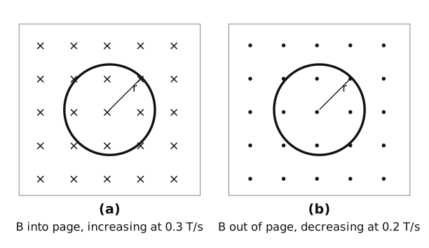
- GUJCET 2025Set 031 markMCQQ.As shown in figure two identical conducting rings of radius r are placed in magnetic field. In figure(a) magnetic field increasing at the rate of 0.3 T/s and in figure(b) magnetic field decreasing at the rate of 0.2 T/s. The direction of current in ring(a) and ring(b), when observe from top are ______. [FIGURE:(a) a ring in a magnetic field directed into the page (crosses);(b) a ring in a magnetic field directed out of the page (dots).] (A) Clockwise, Anticlockwise (B) Anticlockwise, Anticlockwise (C) Clockwise, Clockwise (D) Anticlockwise, Clockwise
›Reveal solutionSolution
[!TLDR] Ring (a): into-page flux increasing -> induced current opposes it by making an out-of-page field -> anticlockwise. Ring (b): out-of-page flux decreasing -> induced current opposes by maintaining the out-of-page field -> anticlockwise. Both anticlockwise.
Apply Lenz's law, viewing each ring from the top (the reader's side), where x = into page (away from viewer) and . = out of page (toward viewer).
Ring (a): The field is into the page (x) and increasing, so into-page flux is growing. The induced current opposes this change and must create a magnetic field OUT of the page inside the ring. By the right-hand rule, a current producing an out-of-page field flows anticlockwise (as seen from the top).
Ring (b): The field is out of the page (.) and decreasing, so out-of-page flux is shrinking. The induced current opposes this by trying to maintain the out-of-page field, i.e. it also creates an out-of-page field inside the ring -> anticlockwise.
Therefore ring (a) is anticlockwise and ring (b) is anticlockwise.
[!ANSWER] Anticlockwise, Anticlockwise.
ANSWER: (B)
Two identical conducting rings of radius r shown in a magnetic field, viewed from the top - GUJCET 2025Set 031 markMCQQ.In an AC generator, induced emf ε=0 at t=0, then its value ______. (A) minimum at time 3ω2π (B) minimum at time 2ωπ (C) maximum at time ω2π (D) maximum at time 2ωπ
›Reveal solutionSolution
[!TLDR]
With ε=ε0sinωt (zero at t=0), the emf is maximum at t=2ωπ — option (D).
Concept
In an AC generator the induced emf is sinusoidal. The condition ε=0 at t=0 selects the sine form:
ε=ε0sin(ωt).
A sine function reaches its maximum value when its argument equals 2π.
Solution
Set ωt=2π:
t=2ωπ.
So the emf first becomes maximum at t=2ωπ.
[!ANSWER]
(D)
- GUJCET 2024Set 131 markMCQQ.A square loop of side 10 cm and resistance 0.5Ω is placed vertically in the east-west plane. A uniform magnetic field of 0.10 T is setup across the plane in the north-east direction. The magnetic field is decreased to zero in 0.70 S at a steady rate. Then the magnitude of induced current during this time interval will be ________. (A) 8.0×10⁻³ A (B) 4.0×10⁻³ A (C) 6.0×10⁻³ A (D) 2.0×10⁻³ A
›Reveal solutionSolution
Induced I=RΔtΔΦ, with the NE field making 45∘ to the loop's normal.
Concept. EMF =ΔtΔΦ; the normal to the east–west vertical plane points N–S, so a NE field makes 45∘ with it.
Area A=(0.10)2=0.01m2.
Φi=BAcos45∘=0.10×0.01×0.707=7.07×10⁻⁴Wb, Φf=0.
ε=ΔtΔΦ=0.707.07×10−4=1.01×10⁻³V.
I=Rε=0.51.01×10−3≈2.0×10⁻³A.
✓Final answerOption (D) 2.0×10⁻³A
ANSWER: (D)
- GUJCET 2024Set 131 markMCQQ.If the primary coil of a transformer has 100 turns and the secondary has 200 turns. Then for a input of 220 V at 10 A find output current, in step up transformer. (A) 5.0 A (B) 50.0 A (C) 0.5 A (D) 0.05 A
›Reveal solutionSolution
Ideal transformer: Is/Ip=Np/Ns (current steps down when voltage steps up).
Concept. Power conserved ⇒VpIp=VsIs and NpNs=VpVs=IsIp.
Is=IpNsNp=10×200100=5.0A.
✓Final answerOption (A) 5.0A
ANSWER: (A)
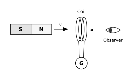
- GUJCET 2023Set 091 markMCQQ.As shown in the figure a bar magnet is moving towards a stationary coil with constant speed v. The direction of induced current in the coil observed by the observer on R.H.S. is ______. [FIGURE: bar magnet with S on left and N on right moving right (velocity v) towards a coil; a galvanometer G is connected; observer stands to the right of the coil] (A) Anticlockwise (B) Clockwise (C) Current changes its direction randomly (D) Induced current will not be produced
›Reveal solutionSolution
[!TLDR] The approaching N pole makes the coil's near face a North pole (Lenz's law); its far face - the one the R.H.S. observer sees - is therefore a South pole, which appears as a clockwise current.
The magnet's N pole moves toward the coil, so the coil flux directed away from the magnet increases. By Lenz's law the induced current opposes this change, so the coil's face nearest the magnet (its left face) becomes a North pole to repel the incoming N pole. Consequently the coil's opposite face - the right-hand face, which the observer on the R.H.S. is looking at - behaves as a South pole. For an observer facing a magnetic South pole of a current loop, the induced current circulates clockwise (the loop's magnetic moment points toward the magnet, i.e. away from the observer, so the current appears clockwise from the observer's side).
[!ANSWER] The observer on the R.H.S. sees the induced current flowing clockwise.
ANSWER: (B)
A bar magnet lies horizontally on the left with its S pole on the left end and N pole on t - GUJCET 2023Set 091 markMCQQ.A circular coil of area 2 cm2 is placed in a magnetic field of 3T perpendicularly. The coil has 10 turns and 5 Ω resistance. Now the coil is removed from magnetic field in 0.2 s. The value of induced charge flowing through the coil is ______. (A) 1.1 mC (B) 1.9 mC (C) 1.2 mC (D) Zero
›Reveal solutionSolution
[!TLDR]
q=NBA/R=1.2 mC (time is irrelevant); option (C).
Concept
When flux through a coil changes, the charge that flows is
q=∫idt=RNΔΦ,
which depends only on the total flux change and resistance, not on how fast it happens. Here ΔΦ=BA (flux goes from BA to 0).
Solution
Data: N=10, B=3 T, A=2 cm2=2×10⁻⁴ m2, R=5Ω.
q=RNBA=510×3×2×10−4=56×10−3×10= ...
=510×3×2×10−4=560×10−4=12×10−4=1.2×10⁻³ C=1.2 mC.
The 0.2 s is a distractor since q is time-independent. Hence option (C).
[!ANSWER]
(C) 1.2 mC
- GSEB Higher Secondary Certificate (HSC) Examination 2023Set ANNUAL1 markMCQQ.A square of side L meter lies in the x-y plane in a region where the magnetic field is given by B (vector) = B_0 (2 i + 4 j + 3 k) T, where B_0 is constant. The magnitude of flux passing through the square is ___.(a) 4 B_0 L^2 Wb(b) 3 B_0 L^2 Wb(c) 2 B_0 L^2 Wb(d) sqrt(29) B_0 L^2 Wb
›Reveal solutionSolution
The square lies in the x-y plane, so its area vector is along z; only the k-component (3 B_0) of B contributes: flux = 3 B_0 L^2.
The square (side L) lies in the x-y plane, so its area vector is A = L^2 k-hat (along z).
Flux Phi = B . A = [B_0(2 i + 4 j + 3 k)] . (L^2 k) = 3 B_0 L^2 (only the k-component survives the dot product).
✓Final answer(b) 3 B_0 L^2 Wb.
- GSEB Higher Secondary Certificate (HSC) Examination 2023Set ANNUAL1 markMCQQ.Magnetic flux linked with the coil is given by phi(t) = (2t^2 + 2t + 1) Wb and its resistance is 10 ohm. The current passing through the coil at t = 2 s is ___ A.(a) 1.5(b) 1(c) 0.5(d) 2
›Reveal solutionSolution
Induced emf = -dphi/dt = -(4t+2); at t = 2, magnitude = 10 V, giving I = 10/10 = 1 A.
Flux phi(t) = 2t^2 + 2t + 1. Induced emf:
e = -dphi/dt = -(4t + 2).
At t = 2 s: |e| = 4(2) + 2 = 10 V.
Current: I = |e|/R = 10/10 = 1 A.
✓Final answer(b) 1 A.
- GUJCET 2022Set 171 markMCQQ."The polarity of induced emf is such that it tends to produce a current which opposes the change in magnetic flux that produced it." This statement is known as ________. (A) Faraday (B) Maxwell (C) Kirchhoff (D) Lenz
›Reveal solutionSolution
The induced current opposing the change in flux that produced it is Lenz's law.
Concept: Lenz's law states that the polarity of the induced emf is such that the induced current opposes the change in magnetic flux causing it — a consequence of conservation of energy.
✓Final answer(D) Lenz
ANSWER: (D)
- GSEB Higher Secondary Certificate (HSC) Examination 2022Set ANNUAL1 markMCQQ.A current-carrying coil with N turns and cross-sectional area A is placed in a uniform magnetic field of magnitude B such that its plane remains perpendicular to the magnetic field. If the number of turns of the coil is now doubled, the magnetic flux linked with it = ______.(a) N^2 B A(b) N B A / 2(c) N B A(d) 2 N B A
›Reveal solutionSolution
Flux linkage scales directly with the number of turns; doubling N doubles the flux linked with the coil.
Magnetic flux through a single loop with plane perpendicular to B: Φ=BA (since normal is parallel to B, cosθ=1).
For N turns, total flux linkage is NΦ=NBA.
If turns are doubled to 2N, the new flux linkage is 2N⋅BA=2NBA.
✓Final answer(d) 2NBA.
🎓Unlock everything free for 14 days
- ✓Full step-by-step solutions
- ✓Concept-first explanations
- ✓Methods, shortcuts & mistakes
- ✓PYQ mapping + timed mock tests
Full access for 14 days. No credit card required.