Q.The electrical resistance in ohms of a certain thermometer varies with temperature according to the approximate law:
[!FORMULA]
R=R0[1+α(T−T0)]
The resistance is 101.6 Ω at the triple-point of water 273.16 K, and 165.5 Ω at the normal melting point of lead (600.5 K). What is the temperature when the resistance is 123.4 Ω?
Concept understanding — Linear Temperature Dependence
Linear Temperature Dependence – First Encounter
You've probably noticed that many things change when you heat them up. A metal rail expands on a hot day. The resistance of a wire increases when current makes it hot. The pressure in a sealed tyre rises after a long drive.
The simplest way this happens is linear temperature dependence — the property changes in direct proportion to the change in temperature. Double the temperature rise, double the change in the property. No surprises, no sudden jumps.
The Intuition
Imagine a rubber band. If you pull it gently, it stretches a little. Pull twice as hard, it stretches twice as much — that's a linear relationship between force and stretch.
Now replace "force" with "temperature change" and "stretch" with "some physical quantity" (length, resistance, pressure, volume). That's linear temperature dependence: equal increments of temperature produce equal increments of the quantity.
This is the first approximation for most materials over a limited temperature range. It's never perfectly true forever, but it's remarkably accurate for small temperature changes.
The Precise Statement
If a physical quantity Q depends linearly on temperature T, then:
Q(T)=Q0+α(T−T0)
Where:
- Q0 is the value at some reference temperature T0 (often 0∘C or 25∘C)
- α is the temperature coefficient — the rate of change per degree
- T is the current temperature
The change ΔQ=Q−Q0 is directly proportional to the change ΔT=T−T0:
ΔQ=αΔT
Q(T)=Q0[1+β(T−T0)]
where β=α/Q0 is the fractional temperature coefficient (units: ∘C−1 or K−1)
Real Examples You'll Meet in Exams
| Quantity | Symbol | Typical behaviour | Common β value |
|---|---|---|---|
| Length of a metal rod | L | Expands on heating | ≈1.2×10⁻⁵∘C−1 (steel) |
| Resistance of a copper wire | R | Increases with temperature | ≈3.9×10⁻³∘C−1 |
| Volume of an ideal gas (constant pressure) | V | Increases linearly with T (in Kelvin) | 1/273.15∘C−1 |
| Pressure of an ideal gas (constant volume) | P | Increases linearly with T (in Kelvin) | 1/273.15∘C−1 |
For gases, the linear law works only when temperature is measured in Kelvin, not Celsius. The formula becomes V=V0(1+273.15T) where T is in °C — but this is just a disguised version of V∝T (Kelvin).
Why This Matters
Linear temperature dependence is the foundation of:
- Thermometers (mercury in glass, resistance thermometers, thermocouples)
- Thermal expansion calculations in bridges and railway tracks
- Temperature compensation in electronic circuits
- Charles's Law and Gay-Lussac's Law for ideal gases
The key insight: when you see a straight-line graph of a physical quantity against temperature, you're looking at linear temperature dependence. The slope of that line is α, and the intercept at T=0 (or T=T0) gives you Q0.
Linear temperature dependence is not a law of nature — it's an approximation that works well for small temperature ranges. For large temperature changes, higher-order terms (T2, T3, ...) become important, and the relationship becomes non-linear.
Students preparing for boards often pair a search for "Linear Temperature Dependence class 11 physics" with "NCERT Physics syllabus" — Linear Temperature Dependence is a syllabus-aligned topic under Thermal Properties of Matter in NCERT Class 11 Physics, making it a natural fit for both board exams and JEE/NEET practice sets. Working through the worked examples above alongside the official NCERT Physics textbook is the most reliable way to turn this understanding into exam-ready recall.
Since R=R0[1+α(T−T0)] is linear, resistance changes are proportional to temperature changes between the calibration points (273.16 K,101.6Ω) and (600.5 K,165.5Ω):
R1−R0R−R0=T1−T0T−T0⇒63.921.8=327.34T−273.16.
T−273.16≈111.7⇒T≈384.9 K.
The temperature is approximately 384.9 K (≈385 K, or 111.7∘C).
Treating the resistance-temperature relation as linear between the two known calibration points, interpolation gives T≈384.9 K (about 385 K, or 111.7∘C) for a resistance of 123.4 Ω.
The relation R=R0[1+α(T−T0)] says resistance changes in direct proportion to temperature above the reference point T0=273.16 K (the triple point of water), where R0=101.6 Ω. Since it's linear, the ratio of resistance changes equals the ratio of temperature changes between any two points on the line.
Setting up the ratio
We know two points on the line: (273.16 K,101.6 Ω) and (600.5 K,165.5 Ω). For the unknown point (T,123.4 Ω):
R1−R0R−R0=T1−T0T−T0.
Substituting values
165.5−101.6123.4−101.6=600.5−273.16T−273.16
63.921.8=327.34T−273.16
Solving for T
T−273.16=63.921.8×327.34≈111.7 K
T≈273.16+111.7≈384.9 K.
Rounding to match the precision of the data, T≈385 K, or equivalently about 111.7∘C.
This linear-interpolation method sidesteps solving for α explicitly - dividing the two known ratios directly is faster and less error-prone than computing α first and then re-solving.
The temperature is approximately 384.9 K (≈385 K, or 111.7∘C).
As a cross-check, solve for α explicitly instead of using the ratio shortcut, and confirm both routes agree. From the two calibration points: α=T1−T0R1/R0−1=600.5−273.16165.5/101.6−1≈1.921×10−3 K−1. Then for R=123.4 Ω: T=T0+αR/R0−1≈273.16+111.7≈384.9 K — the same result reached a different way. The physical caveat worth flagging: this linear resistance law is only approximate; real platinum-type thermometers deviate slightly from a straight line over wide ranges, which is exactly why a constant-volume gas thermometer (extrapolated to zero pressure) is treated as the true calibration standard rather than any single resistance thermometer.
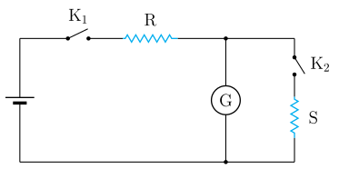
- KCET 2025Set D-41 markMCQQ.In an experiment to determine the figure of merit of a galvanometer by half deflection method, a student constructed the following circuit. He unplugged a resistance of 5200Ω in R. When K1 is closed and K2 is open, the deflection observed in the galvanometer is 26 div. When K2 is also closed and a resistance of 90Ω is removed in S, the deflection between 13 div. The resistance of galvanometer is nearly
 (A) 45.0 Ω
(B) 103.0 Ω
(C) 91.6 Ω
(D) 116.0 Ω
(A) 45.0 Ω
(B) 103.0 Ω
(C) 91.6 Ω
(D) 116.0 Ω›Reveal solutionSolution
Apply the standard half-deflection result G=R−SRS, with R=5200 Ω (the series resistance) and S=90 Ω (the shunt that halves the deflection).
Step 1 — What happens with K2 open.
Only the series resistance R and the galvanometer G carry the current. If the cell emf is E (internal resistance negligible), the current through the galvanometer is
Ig=R+GE
This produces the full deflection, θ=26 divisions. Since deflection ∝ current through the coil,
26∝R+GE(1)
Step 2 — What happens when K2 is closed.
The shunt S=90 Ω is now in parallel with the galvanometer. Because R≫ the parallel combination (5200 Ω versus at most 90 Ω), the total current drawn from the cell is essentially unchanged:
I≈RE
That current now splits between G and S. By the current-divider rule the fraction through the galvanometer is
Ig′=I⋅G+SS
The observed deflection is halved, to 13 divisions.
Step 3 — Impose the half-deflection condition.
Deflection halves ⇒ the coil current halves:
IgIg′=2613=21
G+SS=21 (of the near-unchanged total)⟹RE⋅G+SS=21⋅R+GE
Working this through (the standard derivation) yields the well-known result
G=R−SRS
Why this form? In the ideal limit the shunt must carry exactly as much current as the coil for the coil current to halve — which requires S=G if the total were fixed. The finite R correction produces the R/(R−S) factor, and because R≫S that factor is only slightly above 1, so G comes out slightly larger than S. We should therefore expect an answer a little above 90 Ω — a useful check before computing.
Step 4 — Substitute the numbers.
G=5200−905200×90=5110468000
G=91.585…≈91.6 Ω
This sits just above S=90 Ω, exactly as anticipated.
Rejecting the distractors: (A) 45.0 Ω is S/2 (halving the wrong quantity); (B) 103 Ω and (D) 116 Ω do not follow from RS/(R−S) with these values.
✓Final answerThe correct option is (C) — 91.6 Ω.
ANSWER: C
- KCET 2019Set A-11 markMCQQ.Masses of three wires of copper are in the ratio 1:3:5 and their lengths are in the ratio 5:3:1. The ratio of their electrical resistance are (A) 1:3:5 (B) 5:3:1 (C) 1:15:125 (D) 125:15:1
›Reveal solutionSolution
Resistance depends on length and cross-sectional area; using mass and density to relate area gives the ratio of resistances as 125:15:1, which corresponds to option (D).
The key idea here is that resistance R of a wire is given by R=ρAL, where ρ is resistivity (same for all wires since they are all copper), L is length, and A is cross-sectional area. We are not given areas directly, but we are given masses and lengths. Since all wires are made of the same material (copper), their densities are equal. Mass m=density×volume=d×(A×L). So A=dLm. Substituting this into the resistance formula lets us express R in terms of m and L alone.
Let’s work through it step by step.
- Write the resistance formula in terms of mass and length. For a wire of resistivity ρ, length L, and cross-sectional area A:
R=ρAL
Since mass m=d⋅A⋅L (where d is density), we have A=dLm. Substitute:
R=ρdLmL=ρmL⋅dL=mρdL2
Because ρ and d are constants for all wires, R∝mL2.
-
Assign the given ratios as actual numbers.
The masses are in the ratio 1:3:5. Let the masses be m1=1k, m2=3k, m3=5k (where k is some constant).
The lengths are in the ratio 5:3:1. Let the lengths be L1=5ℓ, L2=3ℓ, L3=1ℓ.
-
Compute the resistance ratio.
Since R∝mL2, we can write:
R1:R2:R3=m1L12:m2L22:m3L32
Substitute the values:
=1k(5ℓ)2:3k(3ℓ)2:5k(1ℓ)2
=k25ℓ2:3k9ℓ2:5k1ℓ2
Simplify each term:
=25:3:51
- Eliminate fractions to get a clean integer ratio. Multiply each term by 5:
=125:15:1
Watch outA common mistake is to directly use R∝L/A and forget that area itself depends on mass and length. Another pitfall is inverting the mass ratio — since R∝1/m, larger mass means smaller resistance, so the smallest mass gives the largest resistance.
TipNotice that the ratio L2/m quickly gives the answer without needing to compute actual areas. This shortcut works whenever the material (and hence density and resistivity) is the same for all wires.
✓Final answerThe ratio of their electrical resistances is 125:15:1, which is option (D).
- KCET 2018Set A-11 markMCQQ.Two cells of internal resistances r1 and r2 and of same emf are connected in series, across a resistor of resistance R. If the terminal potential difference across the cells of internal resistance r1 is zero, then the value of R is (A) R=2(r1+r2) \ (B) R=r2−r1 \ (C) R=r1−r2 \ (D) R=2(r1−r2)
›Reveal solutionSolution
Write the series current from the loop equation, then impose the condition 'terminal PD of cell 1 =0', i.e. V1=E−Ir1=0.
Step 1 — Current in the series loop.
Two cells of the same emf E in series drive a total emf 2E against the total resistance R+r1+r2:
I=R+r1+r22E
Step 2 — Terminal potential difference of a cell.
A cell delivering current I has terminal PD
V=E−Ir
because the current drops Ir volts inside the cell across its own internal resistance. For the first cell:
V1=E−Ir1
Step 3 — Apply the given condition V1=0.
E−Ir1=0⇒E=Ir1
Physically: the whole emf of cell 1 is consumed internally — it is being 'short-circuited' by the rest of the circuit, so it delivers no useful voltage.
Step 4 — Substitute the current.
E=R+r1+r22Er1
Cancel E (non-zero):
R+r1+r2=2r1
R=r1−r2
Sanity check: this requires r1>r2 — reasonable, since only the cell with the larger internal resistance can have its entire emf eaten up internally.
✓Final answerThe correct option is (C) — R=r1−r2.
ANSWER: C
🎓Unlock everything free for 14 days
- ✓Full step-by-step solutions
- ✓Concept-first explanations
- ✓Methods, shortcuts & mistakes
- ✓PYQ mapping + timed mock tests
Full access for 14 days. No credit card required.