Electronics · Ch 4 — Feedback in Amplifiers
Four types of negative feedback
Four types of negative feedback
In an amplifier both voltage and current can be fed back to the input, and the feedback signal can be connected either in series or in parallel with the input. This gives four basic ways of connecting the feedback signal:
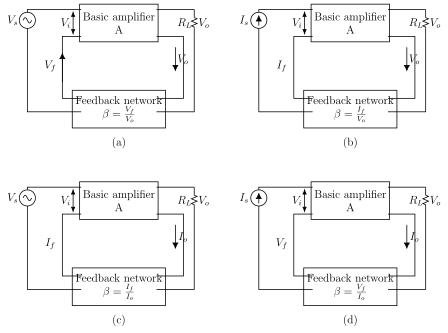
- Voltage series negative feedback — shown in Figure 4.2.1(a). Also called shunt-derived series-fed feedback: a fraction of the output voltage is applied in series with the input voltage through the feedback network.
- Voltage shunt negative feedback — shown in Figure 4.2.1(b). Also called shunt-derived shunt-fed feedback: a small portion of the output voltage is coupled back to the input in parallel (shunt).
- Current series negative feedback — shown in Figure 4.2.1(c). Also called series-derived series-fed feedback: a part of the output current is made to feed back a proportional voltage in series with the input.
- Current shunt negative feedback — shown in Figure 4.2.1(d). Also called series-derived shunt-fed feedback: the feedback network picks up a part of the output current and develops a feedback voltage in parallel (shunt) with the input voltage.
In each case, the two words describe the output and input sides in turn: the first word (voltage or current) tells us what is sampled at the output, and the second word (series or shunt) tells us how the feedback is connected at the input. …
Drawn by us to help you understand the concept clearly, and verified to make sure it's accurate. For exams, practice from your textbook's own diagram.
Reproduces textbook Figure 4.2.1, four panels (a)-(d). Each panel has a 'Basic amplifier A' block, a 'Feedback network' block, a load resistor and output . (a) Voltage series: a voltage source with the feedback voltage in series at the input, output voltage sampled across , feedback network marked . (b) Voltage shunt: a current source with the feedback current fed in parallel at the input node, output voltage sampled, . (c) Current series: a voltage source input, the output current sampled through , feedback current returned in series, . (d) Current shunt: a current source with into a parallel input node, output current sampled, feedback voltage returned in shunt, . Thi …
| Characteristics | Voltage series | Voltage shunt | Current series | Current shunt |
|---|---|---|---|---|
| Voltage gain | decreases | decreases | decreases | decreases |
| Input impedance | increases | decreases | increases | decreases |