Electronics · Ch 4 — Feedback in Amplifiers
Introduction to Feedback
Introduction to Feedback
The important characteristics of an amplifier are its voltage gain, input impedance, output impedance and bandwidth. For a given basic amplifier these parameters are more or less constant — the amplifier has fixed values and the designer has no direct control over them. Quite often, however, we need to change these values. This can be done in several ways; for example, the voltage gain can be reduced with a resistive network at the input or output, and the input impedance can be raised by adding a series resistance. The trouble with such crude methods is that they waste useful signal. A far more powerful technique is to introduce feedback into the amplifier circuit.
In feedback, we sample the output of the basic amplifier and compare that sample against the input signal. In other words, feedback is the process of taking a part of the output signal and feeding it back to the input circuit. The difference between the output sample and the input produces an error signal, which is fed into the input to reduce the error or to control the output.
Principle of feedback in amplifiers
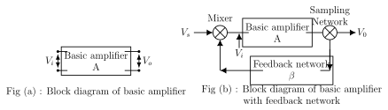
Figure 4.1.1(a) shows the block diagram of a basic amplifier. Here is the input voltage and is the output voltage. If is the voltage gain of the amplifier, the output is related to the input by
In such an amplifier, if the output changes for some reason, the net input remains unaffected. This is called an open-loop (non-feedback) system, and its voltage gain is called the open-loop gain, .
Figure 4.1.1(b) shows the same amplifier with a feedback path added. A sample of the output is returned to the input through a network called the feedback network (the network). A fraction of the output voltage goes back to the input, changing the net input to the amplifier — so the input is now modified by the output. This is called a closed-loop (feedback) system, and the voltage gain of the amplifier with the feedback network is called the closed-loop gain, :
The block diagram of the feedback system uses three functional blocks: a mixer, which combines the source signal with the returned feedback signal to form the amplifier input ; the basic amplifier of gain ; and a sampling network, which taps a portion of the output and passes it to the feedback network before it returns to the mixer.
Feedback ratio and loop gain …
Drawn by us to help you understand the concept clearly, and verified to make sure it's accurate. For exams, practice from your textbook's own diagram.
Reproduces textbook Figure 4.1.1. Fig(a) is a plain basic amplifier: an input drives a block 'Basic amplifier A' whose output is . Fig(b) adds feedback: the source enters a mixer node, whose output feeds the 'Basic amplifier A'; the amplifier output passes through a sampling network to become , and a branch feeds the 'Feedback network ', which returns the sampled signal to the mixer. This figure matters because it defines the standard feedback block model — mixer, …
— voltage gain of the basic amplifier without feedback, where is the input to the amplifier and is its output. It is a dimensionless ratio and describes the open-loop (non-feedback) system, in which a change in the output le …
— voltage gain of the amplifier with the feedback network, where is the source signal applied to the whole feedback system. It is the gain of the closed-loop feedback system, measured with the feedback network in place, and for negative feed …
— the fraction of the output voltage returned to the input, where is the feedback voltage. Also called the feedback fraction or feedback factor, is a dimensionless quantity fixed by the passive feedback network, and it relates the sampled feedback …
— the product of the open-loop gain and the feedback factor . Being the product of two dimensionless quantities, the loop gain is itself dimensionless; together with the closely related factor it governs nearly …