Electronics · Ch 4 — Feedback in Amplifiers
Voltage series negative feedback
Voltage series negative feedback
In the voltage series negative feedback connection, a fraction of the output voltage is applied in series with the input signal through the feedback network. This is the most important of the four types, and here we analyse in detail how it changes the amplifier's voltage gain, gain stability, input impedance, output impedance and bandwidth.
Expression for voltage gain
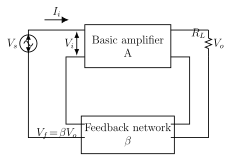
Figure 4.4.1 shows the block diagram. Let be the input to the whole system, the input to the basic amplifier, the feedback voltage and the output voltage.
The open-loop gain gives , so
The closed-loop gain is
The feedback factor gives , so
With negative feedback the input to the basic amplifier is
Rearranging,
Substituting equation (4) into equation (2) and using equation (1),
Thus the voltage gain with negative feedback decreases by a factor of .
Stability in Gain
The closed-loop gain is . When , the '1' in the denominator is negligible, so
The gain then depends only on , and is set by stable passive elements (resistors, capacitors, inductors) in the feedback network. Hence the gain is not affected by changes in device parameters, supply voltage or ageing of components, and the feedback gain is far more stable.
We can quantify this stability. Differentiating with respect to :
Multiplying and dividing the right-hand side by and using ,
Since , the percentage change in the feedback gain is much smaller than the percentage change in the internal gain . This is precisely why negative feedback stabilises the gain.
Increase in Input Impedance
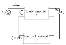
It is desirable for an amplifier to have a high input impedance so that it does not load the preceding stage or the input voltage source. Voltage series negative feedback achieves exactly this (Figure 4.4.2).
Let be the input current, the input to the basic amplifier, the source voltage, the feedback voltage and the output. The input impedance of the basic amplifier is
and the input impedance with feedback is
The input to the basic amplifier is
so
Substituting equation (3) into equation (2) and using equation (1),
Thus the input impedance with negative feedback increases by a factor of .
Decrease in output impedance
An amplifier with low output impedance can deliver voltage or power to the load without much loss. Voltage series negative feedback provides this too.
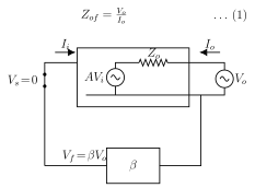
The output impedance of the feedback amplifier is the ratio of output voltage to output current with the input shorted. Let be the output impedance of the basic amplifier and that of the feedback amplifier. To find it, a hypothetical voltage source is applied at the output (Figure 4.4.3), and the amplifier is modelled as a dependent source in series with its internal impedance :
Applying KVL to the output loop,
The input with negative feedback is , but the input is short-circuited so , giving . Substituting into equation (2),
Thus the output impedance with negative feedback decreases by a factor of .
Frequency response of negative feedback amplifier
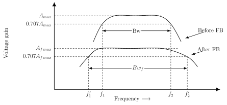
The bandwidth (BW) of an amplifier without feedback is the separation between its 3 dB frequencies and (Figure 4.4.4):
…
Drawn by us to help you understand the concept clearly, and verified to make sure it's accurate. For exams, practice from your textbook's own diagram.
Reproduces textbook Figure 4.4.1. The source is in series with the input; input current enters the basic amplifier of gain as ; the output appears as across the load resistor ; the 'Feedback network ' samples the output voltage across and returns in series with the input. This figure matters because it is the refe …
— the voltage gain with negative feedback, reduced from the open-loop gain by the factor . Here is the open-loop gain and the feedback fraction; since , the closed-loop gain is always smaller than — the price paid for t …
when — the gain then depends only on the stable feedback fraction , making it independent of device parameters, supply voltage and ageing. Because is fixed by stable passive elements (resistors, capacitors, inductors) in the feedback network, the clos …
— since , a given percentage change in the internal gain produces a much smaller percentage cha …
Drawn by us to help you understand the concept clearly, and verified to make sure it's accurate. For exams, practice from your textbook's own diagram.
Reproduces textbook Figure 4.4.2, the same voltage-series topology as Figure 4.4.1 but drawn to analyse input impedance. The input current flows from the source into of the basic amplifier; the output across is sampled by the 'Feedback network ', which returns in series with the input. This figure matters because it defines the loop used to compute $Z_i …
— voltage series negative feedback raises the input impedance by the factor , where is the input impedance of the basic amplifier. A high input impedance is desirable so the amplifier does not load the preceding stage or the input source; this result fo …
Drawn by us to help you understand the concept clearly, and verified to make sure it's accurate. For exams, practice from your textbook's own diagram.
Reproduces textbook Figure 4.4.3, an equivalent circuit for the output-impedance derivation. The input is short-circuited (); the basic amplifier is modelled as a dependent voltage source in series with its internal output impedance ; a hypothetical external source is applied at the output, driving current into the loop; the feedback network returns to the shorted input. This figure matters because applying KVL around the o …
— voltage series negative feedback lowers the output impedance by the factor , where is the output impedance of the basic amplifier. A low output impedance lets the amplifier deliver voltage or power to the load with little loss; it is derived with the …
Drawn by us to help you understand the concept clearly, and verified to make sure it's accurate. For exams, practice from your textbook's own diagram.
Reproduces textbook Figure 4.4.4, a gain-versus-frequency graph. The 'Before FB' curve peaks at with 3 dB points at and (the 0.707 level) and bandwidth . The 'After FB' curve is lower (peak ) but wider, with 3 dB points (below ) and (above ) and bandwidth . This figure matters because it shows visually that negative feedback reduces gain but increases …
and — the bandwidth increases by the same factor by which the gain decreases, so the gain-bandwidth product stays constant. The lower cut-off falls to and the upper rises to , so th …