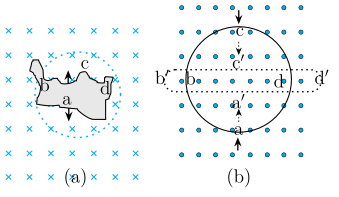
Q.Use Lenz's law to determine the direction of induced current in the situations described by Fig. 6.16:
Concept understanding — Electromagnetic Induction
Electromagnetic Induction
Electromagnetic induction is the phenomenon in which a changing magnetic flux through a circuit produces an electromotive force (emf) — and hence a current, if the circuit is closed. It is the single idea behind generators, transformers, inductors, and the entire AC power grid.
The Central Discovery
Michael Faraday found (1831) that a current is induced in a coil not when a magnet sits still near it, but only while the magnet moves — that is, only while the magnetic flux linked with the coil is changing. A steady magnet, however strong, induces nothing.
Magnetic Flux
The key quantity is magnetic flux ΦB through a surface of area A in a field B:
ΦB=B⋅A=BAcosθ
where θ is the angle between B and the area's normal. Its SI unit is the weber (Wb), where 1 Wb=1 T⋅m2.
Flux can change in three distinct ways, and any of them induces an emf:
- the field strength B changes,
- the area A of the loop changes,
- the orientation θ changes (a coil rotating in a field — the basis of the generator).
Faraday's Law
The induced emf equals the negative rate of change of flux. For a coil of N turns:
E=−NdtdΦB
The faster the flux changes, the larger the emf. This is why a magnet dropped quickly through a coil gives a bigger deflection than one moved slowly.
Lenz's Law — the Minus Sign
The negative sign expresses Lenz's law: the induced current flows in the direction that opposes the change producing it. Push a magnet's north pole toward a coil, and the coil's near face becomes a north pole to repel it; pull it away, and the face becomes a south pole to attract it. This is simply energy conservation — you must do work against this opposition, and that work becomes the electrical energy of the induced current.
Motional emf
A special, very useful case: a conducting rod of length l moving with speed v perpendicular to a field B sweeps out area and develops an emf
E=Blv
Here the emf arises because the free charges in the rod experience a magnetic force qv×B, which drives them along the rod.
Induction does not require physical contact or a battery. It is the change of flux that matters, not its value. A loop sitting in a huge but constant field has zero induced emf.
Where It Leads
Once a coil's own changing current induces an emf in itself, we call it self-inductance (L); when one coil's changing current induces emf in a neighbour, that is mutual inductance (M). Both are direct consequences of Faraday's law. Rotate a coil steadily in a magnetic field and the sinusoidal emf it produces is exactly the alternating voltage that runs the AC circuits studied in this chapter.
Faraday's and Lenz's laws of electromagnetic induction form one of the highest-weightage chapters in NCERT Class 12 Physics, tested extensively in CBSE boards, JEE Main and NEET. Anyone searching "Faraday's law of electromagnetic induction formula and examples class 12 physics" will find this changing-flux explanation, including the motional emf case, is exactly how NCERT presents the chapter.
Why this formula?
Electromagnetic Induction
Electromagnetic induction is the effect discovered by Faraday: a changing magnetic flux through a circuit drives an induced EMF (and hence a current). The key word is changing — a steady field, however strong, induces nothing.
Magnetic flux
Flux measures how many field lines thread a surface bounded by the loop:
ΦB=∫B⋅dA=BAcosθ
It can change three ways: by changing B, by changing the area A, or by rotating the loop (changing θ).
Faraday's law
The induced EMF equals the rate of change of flux:
E=−dtdΦB
For a coil of N turns, E=−NdtdΦB. The EMF depends on how fast the flux changes, not on the flux itself — a slow change gives a small EMF, a rapid change a large one.
Lenz's law — the minus sign
The negative sign is Lenz's law: the induced current flows in the direction that opposes the change producing it. Push a magnet's north pole toward a coil and the coil's near face becomes a north pole to repel it; pull it away and the face becomes a south pole to attract it. This opposition is required by energy conservation — you must do work against the induced current, and that work is what becomes electrical energy. If the current instead aided the change, energy would be created from nothing.
A worked idea
A rod of length l slides at speed v along rails in a field B. In time dt it sweeps area lvdt, so the flux changes by dΦB=Blvdt, giving a motional EMF:
E=dtdΦB=Blv
The same result follows from the magnetic force q(v×B) pushing free electrons to one end of the rod — a direct check that Faraday's law and the Lorentz force tell one consistent story.
The key idea is Lenz’s law: the induced current opposes the change in magnetic flux through the loop.
(a) Irregular shape → circle
- The magnetic field is into the page (⊗). As the loop becomes circular, its area increases, so the flux into the page increases.
- To oppose this increase, the induced current must produce its own magnetic field out of the page (⊙).
- By the right-hand rule, a current that gives an out-of-page field inside the loop must flow anticlockwise (as seen from above).
(b) Circular loop → narrow straight wire
- The magnetic field is out of the page (⊙). As the loop is squeezed into a narrow line, its area decreases, so the flux out of the page decreases.
- To oppose this decrease, the induced current must produce its own magnetic field out of the page (⊙) — i.e., it tries to maintain the original flux.
- By the right-hand rule, a current that gives an out-of-page field inside the loop must flow anticlockwise (as seen from above).
- Anticlockwise;
- Anticlockwise.
Lenz’s law says induced current opposes the change in magnetic flux. In (a), area increases → flux into page increases → induced current creates flux out of page → anticlockwise. In (b), area decreases → flux out of page decreases → induced current creates flux out of page → anticlockwise.
The Core Idea
Lenz’s law is the most elegant way to find induced current direction without getting tangled in right-hand rules. It states: the induced current flows in such a direction that its magnetic field opposes the change in the original magnetic flux through the loop. Think of it as the loop “fighting back” against whatever is happening to it — if flux is increasing, the loop tries to decrease it; if flux is decreasing, the loop tries to increase it.
In both parts of this problem, the magnetic field is uniform and constant. The only thing changing is the area of the loop. So the flux change comes purely from area change, and the induced current’s job is to oppose that area-driven flux change.
(a) Irregular wire turning into a circular shape
1. Identify the initial and final flux.
The field is uniform and directed into the page (shown by × marks). The wire starts as an irregular closed loop and is reshaped into a circle. A circle encloses the maximum area for a given perimeter, so the area increases as the shape becomes circular. Since B is constant and into the page, the magnetic flux Φ=BA also increases.
2. Apply Lenz’s law.
Flux into the page is increasing. The induced current must create its own magnetic field that opposes this increase — that is, it must produce flux out of the page (to cancel some of the incoming flux).
3. Determine the current direction.
To produce a magnetic field out of the page, the induced current must flow anticlockwise (as seen from above). Use the right-hand grip rule: curl your fingers in the direction of current; your thumb points in the direction of the magnetic field inside the loop. Anticlockwise current gives a field out of the page.
A common mistake is to think that because the area increases, the induced current should somehow “help” the increase. Lenz’s law says the opposite — the induced effect always opposes the change, not the existing flux itself.
(b) Circular loop being deformed into a narrow straight wire
1. Identify the initial and final flux.
Here the field is uniform and directed out of the page (shown by • dots). The loop starts as a circle and is squeezed into a narrow straight wire. As it narrows, the enclosed area decreases dramatically — eventually approaching zero. So the flux Φ=BA (out of the page) decreases.
2. Apply Lenz’s law.
Flux out of the page is decreasing. The induced current must oppose this decrease — that is, it must try to increase the out-of-page flux. So it must produce its own magnetic field out of the page.
3. Determine the current direction.
To produce a field out of the page, the induced current must again flow anticlockwise (same reasoning as part (a)).
Both parts give the same direction (anticlockwise) but for opposite reasons: in (a) the induced field opposes an increase in into-page flux, while in (b) it opposes a decrease in out-of-page flux. Always focus on what is changing, not what is constant.
In both cases, the induced current flows anticlockwise as seen from above.
Method: Lenz's Law When the Loop's Shape (Not Its Position) Changes
Some induction problems keep the loop in a fixed, uniform field but deform its shape — the induced current still comes from the resulting change in enclosed area, reasoned the same way as a loop physically leaving a field.
Steps
Step 1: Compare the enclosed area before and after the deformation
Reshaping a loop of fixed wire length (perimeter) changes its enclosed area because different shapes enclose different areas for the same perimeter — a circle encloses the maximum possible area for a given perimeter, so deforming towards a circle increases area, and squeezing a loop into a thin line drives the area towards zero.
Step 2: Translate the area change into a flux change
With B uniform and constant,
ΦB=BA
so the sign of dΦB/dt follows directly from whether A is growing or shrinking.
Step 3: Apply Lenz's law to the flux trend
- Area (and hence flux) increasing → induced current opposes the increase → induced field points opposite to B.
- Area (and hence flux) decreasing → induced current opposes the decrease → induced field points the same way as B.
Step 4: Convert the required induced-field direction into a current direction
Use the right-hand grip rule: point your thumb along the induced field direction found in Step 3, and your curled fingers give the sense of the induced current around the loop.
Note the key insight: the shape of the loop (circle, irregular polygon, narrow line) never affects the direction rule itself — only whether the enclosed area, and hence the flux, is growing or shrinking matters. Two deformations that change flux for opposite reasons (one increasing into-page flux, one decreasing out-of-page flux) can still give the same current direction, because in both cases the induced current is trying to preserve the original flux value.
Showing the 12 most recent of 27 on this concept.
- COMEDK 2026Set 2026-A1 markMCQQ.A metallic circular loop is placed with its plane perpendicular to a uniform magnetic field of 0.3 T . If the radius of the loop decreases at a constant rate of 2 mm s−1, what will be the induced emf in the loop, when the radius of the loop becomes 5 cm . (A) 1.5×10⁻⁶V (B) 0.75×10⁻⁶V (C) 1.84×10⁻⁶V (D) 1.89×10⁻⁴V
›Reveal solutionSolution
The induced emf is found from Faraday’s law: the rate of change of magnetic flux through the loop equals B⋅dA/dt. As the radius shrinks, the area decreases, giving an emf of 1.884×10⁻⁵V, which matches option (D).
The key concept is Faraday’s law of electromagnetic induction: the induced emf in a loop equals the negative rate of change of magnetic flux through it. Here, the magnetic field is uniform and perpendicular to the loop, so the flux is simply Φ=B⋅A, where A=πr2 is the area. Since B is constant, the only change comes from the shrinking radius. The induced emf is therefore ∣E∣=B⋅dtdA. We don’t need to worry about sign for magnitude.
-
Identify the given data
- Magnetic field: B=0.3 T (constant, perpendicular to loop)
- Rate of change of radius: dtdr=−2 mm/s=−2×10−3 m/s (negative because radius decreases)
- Radius at the instant of interest: r=5 cm=0.05 m
-
Relate area change to radius change
Area of the loop: A=πr2
Differentiate with respect to time:
dtdA=dtd(πr2)=2πrdtdr
This is a straightforward chain rule — the area changes because the radius changes.
- Plug in the numbers At r=0.05 m and dtdr=−2×10⁻³ m/s:
dtdA=2π(0.05)(−2×10⁻³)=−2π×10−4 m2/s
The negative sign indicates area is decreasing.
- Apply Faraday’s law Induced emf magnitude:
∣E∣=−dtdΦ=−BdtdA=BdtdA
So:
∣E∣=0.3×(2π×10−4)=0.6π×10−4 V
Using π≈3.1416:
∣E∣=0.6×3.1416×10−4=1.88496×10⁻⁴ V
Rounding gives 1.88×10⁻⁴ V, which is 1.89×10⁻⁴ V in the options.
Watch outA common mistake is to forget that the area depends on r2, so the rate of change of area is 2πrdr/dt, not π(dr/dt)2. Also, watch units: convert mm to m and cm to m consistently.
TipNotice that the induced emf is proportional to the instantaneous radius r, not the initial radius. So you must use r=0.05 m at the moment you want the emf.
✓Final answerThe correct option is (D).
ANSWER: D
-
- COMEDK 2026Set 2026-M1 markMCQQ.A square loop of wire 2.2 cm on each side contains 2 turns and has a total resistance of 0.0002Ω. It is located 22 cm from a long straight current carrying wire. If the current in the straight wire is increased at a steady rate from 20 A to 50 A in 5 s , determine the magnitude of the current induced in the squared loop. (A) 0.26 mA (B) 2.64 mA (C) 0.026 mA (D) 0.0026 mA
›Reveal solutionSolution
The changing current in the straight wire changes the flux through the loop, inducing an emf (Faraday's law); dividing by the resistance gives the current. The result is about 0.026 mA — option (C).
Concept & Intuition
A long straight wire carrying a current creates a magnetic field that circles the wire, with strength B=2πrμ0I at a perpendicular distance r. The square loop near the wire has magnetic flux through it. When the wire's current changes, the flux changes, inducing an emf (Faraday's law); the emf drives a current found from Ohm's law. Because the field varies across the loop, the flux is obtained by integration (a uniform-field estimate at the mean distance gives essentially the same answer here).
Step-by-step solution
- Geometry and field. Side a=2.2 cm=0.022 m, nearest side d=22 cm=0.22 m, N=2 turns, R=0.0002 Ω.
B(r)=2πrμ0I,μ0=4π×10−7 T⋅m/A.
- Flux through one turn (integrating a strip of height a, width dr):
Φ1=∫dd+a2πrμ0Iadr=2πμ0Ialn(dd+a).
- Total flux for N turns:
Φtotal=NΦ1=πμ0Ialn(dd+a).
- Induced emf. With dtdI=550−20=6 A/s:
∣E∣=πμ0aln(dd+a)dtdI.
- Plug in numbers.
dd+a=0.220.242=1.1,ln(1.1)≈0.09531,
∣E∣=4×10−7×0.022×0.09531×6≈5.03×10⁻⁹ V.
- Induced current.
Iinduced=R∣E∣=0.00025.03×10−9≈2.5×10⁻⁵ A=0.025 mA≈0.026 mA.
Watch outA common error is off-by-a-power-of-ten arithmetic — the answer is 0.026 mA, not 0.26 mA.
TipNotice the π cancels neatly — simplify symbolic expressions before plugging numbers.
✓Final answerThe correct option is (C).
ANSWER: C
- COMEDK 2026Set 2026-M1 markMCQQ.A circular coil of radius 7 cm and 40 turns is rotated about its vertical diameter with an angular speed of 40 radians per second in a uniform horizontal magnetic field of 4×10⁻²T. What is the maximum current induced in the coil if the resistance of the coil is 11Ω ? (A) 90 mA (B) 0.9 mA (C) 9 mA (D) 0.09 mA
›Reveal solutionSolution
The maximum induced current is found from the peak emf generated by a rotating coil in a magnetic field: Emax=NBAω, then Imax=Emax/R. The result is 0.09 A = 90 mA, so option (A) is correct.
Concept & Intuition
When a coil rotates in a uniform magnetic field, the magnetic flux through it changes sinusoidally. Faraday’s law tells us that a changing flux induces an emf. The maximum emf occurs when the plane of the coil is parallel to the field (flux changing fastest). For a coil of N turns, area A, rotating at angular speed ω in a field B, the peak induced emf is Emax=NBAω. Then Ohm’s law gives the peak current.
Step-by-step solution
-
Identify the given quantities
- Radius r=7 cm=0.07 m
- Number of turns N=40
- Angular speed ω=40 rad/s
- Magnetic field B=4×10⁻² T
- Resistance R=11 Ω
-
Compute the area of the coil
The coil is circular, so
A=πr2=π(0.07)2=π×0.0049=0.0049π m2
- Find the maximum induced emf For a coil rotating in a uniform field, the flux is Φ=NBAcos(ωt). The induced emf is E=−dΦ/dt=NBAωsin(ωt). The maximum value is
Emax=NBAω
Substitute:
Emax=40×(4×10−2)×(0.0049π)×40
First, 40×40=1600, so
Emax=1600×4×10−2×0.0049π
1600×4×10−2=64, so
Emax=64×0.0049π=0.3136π
Using π≈3.1416,
Emax≈0.3136×3.1416≈0.985 V
- Calculate the maximum induced current By Ohm’s law,
Imax=REmax=110.985≈0.0895 A
That is about 0.09 A=90 mA.
TipNotice that the radius was given in cm — a classic trap is to forget converting to metres. Always check units before plugging into formulas.
Watch outSome might mistakenly use the diameter instead of radius, or forget to multiply by N (number of turns). Both errors lead to answers that match the distractors, so careful step-by-step work is essential.
- Match with the options 90 mA corresponds to option (A).
✓Final answerThe correct option is (A).
ANSWER: A
-
- KCET 2026Set C21 markMCQQ.In Faraday-Henry's experiment, a coil is connected to a galvanometer. For the deflection of pointer in the galvanometer, which of the following statement/s is/are WRONG? The pointer in the galvanometer deflects -(a) When the bar magnet is moved towards the stationary coil along its axis(b) When the bar magnet is moved away from the stationary coil along its axis(c) When the coil is moved towards the stationary bar magnet along its axis(d) When the coil and the magnet are moved without relative motion between them (A) a and b (B) b and c (C) a, b and c (D) Only d
›Reveal solutionSolution
By Faraday's law, an EMF (and hence a galvanometer deflection) is induced only when the magnetic flux through the coil changes — which requires relative motion between the coil and the magnet.
Step 1 — Check (a) and (b): magnet moved relative to stationary coil
When the bar magnet is moved towards or away from the stationary coil along its axis, the flux linked with the coil changes with time, inducing an EMF and deflecting the galvanometer. Both (a) and (b) correctly describe deflection.
Step 2 — Check (c): coil moved relative to stationary magnet
Moving the coil towards the stationary magnet also changes the relative position (and hence the flux through the coil) — the same relative motion that matters, whichever object physically moves. This correctly causes deflection too.
Step 3 — Check (d): both moved together, no relative motion
If the coil and the magnet are moved together with NO relative motion between them, the flux linked with the coil never changes (the coil's position relative to the magnet's field stays fixed). No change in flux means no induced EMF, so there is NO deflection. The statement in (d) — implying deflection still occurs — is therefore the WRONG one.
Conclusion
- (a) — correct, deflection occurs.
- (b) — correct, deflection occurs.
- (c) — correct, deflection occurs.
- (d) — the wrong statement; no deflection occurs since there is no relative motion.
✓Final answerThe correct option is (D) — Only (d) is wrong.
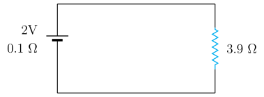
- KCET 2025Set D-41 markMCQQ.In the following circuit, the terminal voltage across the cell is
 (A) 1.68 V
(B) 1.95 V
(C) 2.71 V
(D) 0.52 V
(A) 1.68 V
(B) 1.95 V
(C) 2.71 V
(D) 0.52 V›Reveal solutionSolution
Find the loop current from I=R+rε, then subtract the internal drop: V=ε−Ir.
Step 1 — What "terminal voltage" means.
A real cell is an ideal emf ε in series with an internal resistance r. When current I flows, part of the emf is lost pushing that current through r itself. What is left across the cell's terminals — and what the external circuit actually receives — is the terminal voltage:
V=ε−Ir
Equivalently, V is just the potential difference across the external resistor, V=IR. (Both routes must give the same number — a useful self-check.)
Step 2 — Read the circuit values.
From the diagram:
ε=2 V,r=0.1 Ω,R=3.9 Ω
The cell and the resistor form one closed series loop, so the same current flows through both.
Step 3 — Current from Ohm's law for the complete circuit.
The total resistance in the loop is R+r:
I=R+rε=3.9+0.12=4.02=0.5 A
Step 4 — The internal ("lost") volts.
Ir=(0.5)(0.1)=0.05 V
Step 5 — The terminal voltage.
V=ε−Ir=2−0.05=1.95 V
Step 6 — Cross-check via the external resistor.
V=IR=(0.5)(3.9)=1.95 V✓
The two independent routes agree, confirming the arithmetic.
Sanity note: because r≪R, the terminal voltage should come out only slightly below the emf of 2 V — which 1.95 V is. Option (C), 2.71 V, is impossible: a discharging cell can never deliver more than its emf. Options (A) and (D) are far too low for such a small internal resistance.
✓Final answerThe correct option is (B) — 1.95 V.
ANSWER: B
- KCET 2025Set D-41 markMCQQ.A solenoid is 1m long and 4 cm in diameter. It has five layers of windings of 1000 turns each and carries a current of 7A. The magnetic field at the centre of the solenoid is (A) 0.4396×10⁻⁵ T (B) 4.396×10⁻² T (C) 43.96×10⁻² T (D) 439.6 T
›Reveal solutionSolution
Add the layers to get the total turns, divide by the length for n, and apply B=μ0nI — the diameter is irrelevant.
Step 1 — The formula and why it applies.
For a long solenoid (length ≫ diameter), Ampère's law applied to a rectangular loop straddling the winding gives a field that is uniform inside and essentially zero outside:
B=μ0nI
where n is the number of turns per unit length and I the current. Check the geometry: length =1 m, diameter =4 cm=0.04 m. The ratio is 25:1, comfortably "long", so the formula is valid at the centre.
Note what does not appear: the diameter. The interior field of an ideal solenoid is independent of its radius — the 4 cm is given only as a distractor (and to let you verify the long-solenoid condition).
Step 2 — Count the total turns.
The windings are in five layers of 1000 turns each. Every layer wraps the same 1 m length and every turn of every layer carries the same current in the same sense, so their contributions simply add:
N=5×1000=5000 turns
Step 3 — Turns per unit length.
n=LN=1 m5000=5000 turns m−1
Step 4 — Substitute.
With μ0=4π×10−7 T m A−1 and I=7 A:
B=(4π×10−7)(5000)(7)
First combine the numbers:
5000×7=35000=3.5×10⁴
B=4π×10−7×3.5×104=4×3.1416×3.5×10−3
4×3.1416=12.566;12.566×3.5=43.98
B=43.98×10⁻³ T=4.398×10⁻² T
Step 5 — Match to an option.
4.398×10⁻² T matches option (B), 4.396×10⁻² T, to within rounding of π.
Step 6 — Why the others fail.
- (A) 0.4396×10⁻⁵ T — smaller by a factor of ∼104; this is what you get if the five layers are ignored and a power of ten is dropped.
- (C) 43.96×10⁻² T — ten times too large (a misplaced decimal: 43.98×10⁻³, not ×10−2).
- (D) 439.6 T — physically absurd; fields of that size exist only in the most extreme pulsed laboratory magnets, not in a hand-wound solenoid carrying 7 A.
✓Final answerThe correct option is (B) — 4.396×10⁻² T.
ANSWER: B
- COMEDK 2025Set 2025-A1 markMCQQ.A circular coil of area 22 cm2 and resistance 2Ω is arranged vertically in the east -west direction. A uniform magnetic field 0.2 T is set up across the plane in the north to east direction. Now the magnetic field is removed at a steady rate in 0.4 s What is the current developed in the coil? (A) 0.5×10⁻³A (B) 0.5×10⁻⁴A (C) 1×10⁻⁴A (D) 0.5×10⁻⁵A
›Reveal solutionSolution
The induced current is found from Faraday’s law: the rate of change of magnetic flux through the coil equals the induced emf, which divided by the resistance gives the current. The result is 0.5×10⁻⁴A, so option (B) is correct.
Concept & Intuition
When the magnetic field through a coil changes, an emf is induced. Here the field is uniform initially and then removed steadily, so the flux changes at a constant rate. The key is to find the component of the magnetic field perpendicular to the coil’s plane — only that component contributes to the flux. The coil is vertical and oriented east–west; the field is directed from north to east, so we must resolve it into components relative to the coil’s normal.
Step-by-step solution
-
Identify the geometry
The coil is vertical and its plane faces east–west. That means the normal to the coil’s plane points either north or south (perpendicular to the plane). Let’s take the normal pointing north. The magnetic field of 0.2T is directed from north to east — that is, at 45∘ east of north. So the angle between the field direction and the coil’s normal (north) is 45∘.
-
Compute the initial magnetic flux
Magnetic flux Φ=BAcosθ, where θ is the angle between the field and the normal.
Area A=22cm2=22×10−4m2.
So
Φi=(0.2)×(22×10−4)×cos45∘.
Since cos45∘=21,
Φi=0.2×22×10−4×21=0.2×2×10−4=4×10⁻⁵Wb.
-
Final flux
The field is removed completely, so final flux Φf=0.
-
Induced emf
By Faraday’s law, the magnitude of the induced emf is
∣E∣=ΔtΔΦ=0.44×10⁻⁵−0=1×10⁻⁴V.
- Induced current Using Ohm’s law, I=E/R. Resistance R=2Ω.
I=21×10−4=0.5×10⁻⁴A.
Watch outA common mistake is to forget that only the component of the magnetic field perpendicular to the coil’s plane contributes to flux. Using the full field strength without the cos45∘ factor would give double the correct flux and hence double the current.
TipNotice that the 2 in the area cancels neatly with the cos45∘=1/2, simplifying the arithmetic. Always look for such cancellations in problems with 45∘ angles.
✓Final answerThe correct option is (B).
ANSWER: B
-
- COMEDK 2025Set 2025-E1 markMCQQ.A rectangular coil of 250 turns has an average area of 20 cm×15 cm. The coil rotates with a speed of 60 cycles per second in a uniform magnetic field of 2×10⁻² T about an axis perpendicular to the field. The peak value of the induced emf is: (A) 36π volt (B) 30π volt (C) 18π volt (D) 12π volt
›Reveal solutionSolution
Peak emf ε0=NBAω with ω=2πf: 250×(2×10−2)×(0.03)×120π=18π volt.
Given: N=250 turns, area A=20 cm×15 cm=300 cm2=300×10−4m2=0.03m2, frequency f=60Hz, B=2×10⁻²T.
Angular frequency:
ω=2πf=2π(60)=120π rad/s
Peak (maximum) induced emf of a rotating coil:
ε0=NBAω
ε0=250×(2×10−2)×0.03×120π
Step by step:
250×0.02=5,5×0.03=0.15,0.15×120=18
ε0=18π volt
✓Final answerPeak induced emf =18π volt — option (C).
- COMEDK 2025Set 2025-M1 markMCQQ.The magnetic flux ϕ through a stationary loop of wire having a resistance R varies with time as ϕ=4t2+3t. The average emf and total charge flowing in the loop in the time interval t=0 to t=τ respectively are (A) τ+3,R4τ2+3τ (B) 3τ+4,R4τ2+3τ (C) 4τ+3,R4r+3 (D) 4τ+3,R4τ2+3τ
›Reveal solutionSolution
The average emf is the total change in flux divided by the time interval, giving 4τ+3; the total charge is the total change in flux divided by resistance, giving R4τ2+3τ. The correct option is (D).
The key idea here is that average emf is not the same as instantaneous emf. For a stationary loop, Faraday’s law gives the instantaneous induced emf as E=−dtdϕ. But the average emf over a time interval is simply the total change in magnetic flux divided by that time interval — no calculus needed for the average. Similarly, the total charge that flows is linked to the total change in flux via Q=RΔϕ, because the induced current is I=E/R and charge is the integral of current over time.
Let’s work through it step by step.
- Find the total change in flux from t=0 to t=τ. At t=0: ϕ(0)=4(0)2+3(0)=0. At t=τ: ϕ(τ)=4τ2+3τ. So the total change is
Δϕ=ϕ(τ)−ϕ(0)=4τ2+3τ.
- Average emf is defined as the total change in flux divided by the total time (since emf is the rate of change of flux, its average over an interval is just the net change per unit time).
Average emf=ΔtΔϕ=τ4τ2+3τ=4τ+3.
Notice this is not the same as evaluating −dtdϕ at some midpoint — it’s a pure average.
- Total charge flowing through the loop: The induced current at any instant is I(t)=RE(t)=−R1dtdϕ. The total charge is the integral of current over time:
Q=∫0τI(t)dt=∫0τ−R1dtdϕdt=−R1∫ϕ(0)ϕ(τ)dϕ=−R1(ϕ(τ)−ϕ(0)).
The minus sign just indicates direction; the magnitude of charge is
Q=R∣Δϕ∣=R4τ2+3τ.
TipA neat shortcut: For any induced emf, the total charge that flows depends only on the total change in flux and the resistance, not on how fast the flux changes. So you never need to differentiate — just compute Δϕ/R.
- Match with the options: Average emf = 4τ+3 and total charge = R4τ2+3τ. This matches option (D) exactly.
Watch outA common mistake is to compute the instantaneous emf at t=τ (which is 8τ+3) and mistake that for the average. Always remember: average emf = total flux change / total time, not the derivative at the endpoint.
✓Final answerThe correct option is (D).
ANSWER: D
- COMEDK 2024Set 2024-A1 markMCQQ.A wire ' 1 ' cm long bent into a circular loop is placed perpendicular to the magnetic field of flux density 'B′Wb m−2. Within 0.1sec, the loop is changed into a square of side 'a' cm and flux density is doubled. The value of e.m.f. induced is (A) 2−5B(8лa2−l2) (B) 2л5B(8лa2−l2) (C) 2л−5B(8лa2−l2) (D) 2π−5B(8a2−l2)
›Reveal solutionSolution
The induced emf is found from Faraday’s law by computing the change in magnetic flux through the loop as its shape changes from a circle to a square and the field doubles. The correct expression is option (C).
The key idea is that the induced emf depends only on the rate of change of magnetic flux through the loop. Here, two things change simultaneously: the shape (which alters the area) and the magnetic field strength. The wire length is fixed, so the perimeter of the circle equals the perimeter of the square, giving a relation between the original length l and the square’s side a. We then compute the flux before and after, take the difference, divide by the time interval, and include the negative sign from Lenz’s law.
- Relate the wire length to the square’s side. The wire is l cm long. Bent into a circle, its circumference is l. Bent into a square of side a cm, the perimeter is 4a. Since the same wire is used,
l=4a⇒a=4l.
This is crucial: the problem gives both l and a as symbols, but they are not independent — the square’s side is determined by the wire length. However, the answer choices treat l and a as separate variables, so we must keep both in the final expression, using the relation only to simplify if needed.
- Find the initial area (circular loop). Circumference =l=2πr, so radius r=2πl. Area of circle:
Acircle=πr2=π(2πl)2=4πl2.
- Find the final area (square loop). Side a is given, so area:
Asquare=a2.
(Using the relation a=l/4 would give a2=l2/16, but we keep a as is for the answer.)
- Compute the initial and final magnetic flux. Flux Φ=BA (since field is perpendicular). Initial flux:
Φi=B⋅4πl2.
Final flux: field doubles to 2B, area becomes a2:
Φf=(2B)⋅a2=2Ba2.
- Find the change in flux.
ΔΦ=Φf−Φi=2Ba2−4πBl2.
Factor B:
ΔΦ=B(2a2−4πl2).
- Apply Faraday’s law. Induced emf E=−ΔtΔΦ. Time interval Δt=0.1 s.
E=−0.1B(2a2−4πl2)=−10B(2a2−4πl2).
- Simplify to match the answer choices. Write as a single fraction:
E=−10B(4π8πa2−l2)=−4π10B(8πa2−l2)=−2π5B(8πa2−l2).
This is exactly option (C).
Watch outA common mistake is to forget that the wire length is fixed, so l=4a. But here the answer choices treat l and a as independent symbols — you must not substitute a=l/4 unless the final expression simplifies to one of the options. In this case, substituting would give a different form not listed, so keep both variables.
TipNotice that the factor 0.1 s in the denominator becomes 10 when moved to the numerator. Always check the time interval: here it’s 0.1 s, so the rate factor is 10.
✓Final answerThe correct option is (C).
ANSWER: C
- COMEDK 2024Set 2024-A1 markMCQQ.In an inductor of self-inductance 2 mH, current changes with time (in sec) according to the relation, I=(3t2−3t+8)A. The emf becomes zero at (A) 2 sec (B) 6 sec (C) 0.5 sec (D) 5 sec
›Reveal solutionSolution
The induced emf in an inductor is given by E=−LdtdI. Setting this to zero means dtdI=0. Differentiating I=3t2−3t+8 gives 6t−3=0, so t=0.5 s. The correct option is (C).
The key idea is that the emf across an inductor depends on the rate of change of current, not the current itself. When the current is at a turning point (maximum or minimum), its derivative is zero, so the induced emf vanishes. This is a classic application of Faraday's law in the context of a single inductor.
-
Recall the fundamental relation for an inductor.
The self-induced emf in an inductor is E=−LdtdI, where L is the inductance and dtdI is the instantaneous rate of change of current. The negative sign indicates Lenz’s law, but for finding when the emf is zero, we only care about the magnitude being zero.
-
Set the condition for zero emf.
Since L is a constant (here 2 mH=2×10⁻³ H), E=0 exactly when dtdI=0. So we need to find the time t at which the derivative of the given current function is zero.
-
Differentiate the current function.
Given I(t)=3t2−3t+8, differentiate term by term:
dtdI=dtd(3t2)−dtd(3t)+dtd(8)=6t−3.
-
Solve for t when the derivative is zero.
Set 6t−3=0, so 6t=3, giving t=0.5 seconds.
-
Interpret the result.
At t=0.5 s, the current is at a stationary point (a minimum, since the parabola opens upward). At that instant, the current is not changing, so no emf is induced across the inductor.
TipA common mistake is to set the current itself to zero (I=0) instead of its derivative. But the emf depends on how fast the current changes, not on its value. Here, I(0.5)=3(0.25)−1.5+8=7.25 A — not zero at all, yet the emf is zero.
Watch outDon’t forget that the inductance L is in mH; but since we only set dtdI=0, the value of L doesn’t affect the answer. However, if you were computing the actual emf, you’d need to convert to henries.
✓Final answerThe correct option is (C).
ANSWER: C
-
- COMEDK 2024Set 2024-E1 markMCQQ.A conducting circular loop is placed in a uniform magnetic field B=0.125 T with its plane perpendicular to the loop. If the radius of the loop is made to shrink at a constant rate of 2 mm s−1, then the induced emf when the radius is 4 cm is (A) 0.52πμV (B) 20πμV (C) 32μV (D) 23πμV
›Reveal solutionSolution
The induced emf is found from Faraday’s law: the rate of change of magnetic flux through the loop as its radius shrinks. The result is 20π μV, which corresponds to option (B).
The key idea is that a changing area in a constant magnetic field produces an induced emf. Here, the loop’s radius decreases at a steady rate, so the area shrinks linearly with time. Faraday’s law tells us that the induced emf equals the negative rate of change of magnetic flux. Since the field is uniform and perpendicular to the loop, the flux is simply B×area. The problem gives the rate of change of radius, so we can find the rate of change of area and thus the emf.
- Set up the magnetic flux. The loop’s plane is perpendicular to B, so the flux through one turn is
Φ=B⋅(area)=B⋅πr2.
Here B=0.125 T is constant.
- Apply Faraday’s law. The induced emf is
E=−dtdΦ=−Bπ⋅dtd(r2).
Using the chain rule,
dtd(r2)=2rdtdr.
So
E=−Bπ⋅2rdtdr.
The negative sign indicates direction (Lenz’s law); we care about magnitude.
-
Plug in the numbers at the instant r=4 cm.
- B=0.125 T
- r=4 cm=0.04 m
- dtdr=−2 mm/s=−0.002 m/s (negative because radius is shrinking)
Magnitude of emf:
∣E∣=Bπ⋅2rdtdr=0.125×π×2×0.04×0.002.
- Calculate step by step.
0.125×2=0.25,0.25×0.04=0.01,0.01×0.002=2×10⁻⁵.
So
∣E∣=π×2×10−5=2π×10−5 V.
- Convert to microvolts. 1 μV=10−6 V, so
2π×10−5 V=20π×10−6 V=20π μV.
TipA common mistake is forgetting to convert cm to m and mm/s to m/s. Always work in SI units (metres, seconds) before plugging into formulas.
Watch outSome might mistakenly use the formula for motional emf (Bℓv) on a straight wire, but here the entire loop’s area changes — Faraday’s law for a changing area is the correct approach.
✓Final answerThe correct option is (B).
ANSWER: B
🎓Unlock everything free for 14 days
- ✓Full step-by-step solutions
- ✓Concept-first explanations
- ✓Methods, shortcuts & mistakes
- ✓PYQ mapping + timed mock tests
Full access for 14 days. No credit card required.