Q.A 100 turn closely wound circular coil of radius 10 cm carries a current of 3.2 A.
The coil is placed in a vertical plane and is free to rotate about a horizontal axis which coincides with its diameter. A uniform magnetic field of 2 T in the horizontal direction exists such that initially the axis of the coil is in the direction of the field. The coil rotates through an angle of 90∘ under the influence of the magnetic field.
Concept understanding — Magnetic Force Balance
Magnetic Force Balance
When a current-carrying wire or coil sits in a magnetic field, it feels a force F=BILsinθ (or, for a point charge, F=qvBsinθ). On its own that force just pushes the conductor - but in many real situations the push is deliberately set up to CANCEL another force, so the whole system sits in equilibrium. That equilibrium condition - magnetic force balanced against weight, against another wire's magnetic force, or against a mechanical counterweight - is what "magnetic force balance" means, and it is also historically how the ampere itself was defined.
The balance condition
Whenever a conductor is in equilibrium under a magnetic force and one other force, the two must be equal and opposite:
BILsinθ=Fother
Solving this equation for whichever quantity is unknown (B, I, L, or the other force) is the entire skill in this class of problem - the only new step, beyond the force law itself, is correctly identifying what the magnetic force is opposing.
Case 1: a wire suspended against gravity
A straight horizontal wire of mass m and length l, carrying current I, can be held up ("floated") in mid-air by a horizontal magnetic field perpendicular to it. The upward magnetic force must equal the downward weight:
BIl=mg⟹B=Ilmg
For example, a 200g, 1.5m wire carrying 2A needs B=(2)(1.5)(0.2)(9.8)≈0.65T to stay suspended.
Case 2: two wires balancing each other
Two long parallel wires carrying currents I1,I2 exert a force per unit length on each other of 2πdμ0I1I2 (attractive if the currents run the same way, repulsive if opposite). If one wire is free to move, this magnetic force can itself balance that wire's weight:
2πhμ0I2L=mg⟹h=2πmgμ0I2L
This is exactly how a "current balance" apparatus works, and historically it is how the ampere was defined: the current that, flowing in two infinite parallel wires one metre apart, produces a force of exactly 2×10⁻⁷N per metre of length.
Case 3: balancing on a beam
A current-carrying coil arm hanging from one pan of a beam balance feels an extra force F=NBIl when only that arm sits in an external field. Re-balancing the beam means adding a mass m so that mg=NBIl.
Always check which length enters the formula - for a coil of N turns the force multiplies by N; for a single suspended straight wire it doesn't.
The direction of the magnetic force (via the right-hand rule on IL×B) has to already point the right way to oppose the other force - check direction FIRST, before solving the magnitude equation, or you may set up a balance condition that is physically backwards.
Why this differs from the general force law
The formula F=BILsinθ is common to every problem here - but "magnetic force balance" problems are specifically the ones where the magnetic force is set exactly equal to something else (gravity, another wire's force, a beam's counterweight) so the system sits still. It is this equilibrium framing, not the force law by itself, that defines the concept, and what distinguishes it from the general force-on-a-current topic.
Balancing the magnetic force on a current-carrying conductor against gravity or another wire's force is a classic numerical application from the NCERT Class 12 Physics chapter on moving charges and magnetism, tested in CBSE boards and JEE Main. Students searching "force on a current carrying conductor in magnetic field numericals class 12" will find this equilibrium-condition approach, including the historical current-balance definition of the ampere, matches the NCERT treatment.
Why this formula?
Magnetic Force Balance: Why the Key Formulas Hold
The Magnetic Force Balance describes when the magnetic force on a charged particle or current-carrying conductor is exactly balanced by another force (gravity, electric force, or tension). Let's build the reasoning step-by-step.
1. The Core Idea: What Does "Balance" Mean?
A force balance means the net force on an object is zero:
Fnet=0
For magnetic forces we use the Lorentz force law:
- On a moving charge: Fm=q(v×B)
- On a current-carrying wire: Fm=I(L×B)
When this is balanced by another force (say gravity Fg=mg):
Fm+Fother=0
2. Case 1: Charged Particle in Crossed Fields (Velocity Selector)
A charged particle moves perpendicular to both electric field E and magnetic field B.
- Electric force: Fe=qE (along E)
- Magnetic force: Fm=q(v×B) (perpendicular to both v and B)
For straight-line motion (no deflection), the two forces must cancel:
qE=qvB⇒v=BE
Key insight: Only particles with this exact speed pass undeflected — this is how velocity selectors work in mass spectrometers.
3. Case 2: Current-Carrying Wire Balanced by Gravity
A horizontal wire carrying current I sits in a perpendicular magnetic field B, suspended by strings.
The magnetic force on a straight wire is Fm=ILBsinθ; for a wire perpendicular to the field (θ=90∘), Fm=ILB. Setting this equal to the weight Fg=mg for equilibrium:
ILB=mg
Key insight: This balance lets you measure B if I, L, and m are known — the principle behind a current balance experiment.
4. Case 3: Circular Motion of a Charged Particle
A charged particle moving perpendicular to a uniform magnetic field has the magnetic force supply the centripetal force:
qvB=rmv2⇒r=qBmv
Key insight: The radius depends on momentum (mv) and charge-to-mass ratio — this is why cyclotrons and mass spectrometers work.
5. Quick Summary
| Situation | Balanced Forces | Key Formula |
|---|---|---|
| Velocity selector | qE vs qvB | v=E/B |
| Current balance | ILB vs mg | ILB=mg |
| Circular motion | qvB vs mv2/r | r=mv/(qB) |
Every formula follows the same recipe: identify all forces, set the vector sum to zero (or to ma), and solve along the direction of interest. Because the magnetic force is always perpendicular to both velocity/current and field, getting the direction right matters as much as the magnitude.
Concept: Magnetic Force Balance — the torque on a current loop in a uniform field is τ=m×B, and work done by the field equals the change in rotational kinetic energy.
(a) Field at centre of a circular coil:
B=2Rμ0NI
=2×0.104π×10−7×100×3.2=2.01×10⁻³ T.
(b) Magnetic moment: m=NIA=NI(πR2)
=100×3.2×π×(0.10)2=10.05 A m2.
(c) Torque magnitude: τ=mBsinθ
Initial (θ=0): τi=0
Final (θ=90∘): τf=10.05×2=20.1 N m.
(d) Work done by field = mB(cos0−cos90∘)=mB=20.1 J
This equals 21Iω2:
ω=0.12×20.1=402≈20.05 rad/s.
- 2.0×10⁻³ T,
- 10 A m2,
- 0 and 20 N m,
- 20 rad/s.
The problem uses the magnetic field at the centre of a circular coil, its magnetic moment, and then torque and rotational dynamics. The field is Bc=2.01×10⁻³ T, magnetic moment m=10.05 A m2, initial torque is zero, final torque is 20.1 N m, and the angular speed after 90∘ rotation is ω=20.0 rad/s.
Concept and Intuition
This is a beautiful blend of three ideas: the magnetic field produced by a current-carrying coil, the magnetic moment that governs how the coil interacts with an external field, and the resulting torque that makes it rotate. The key is that the torque depends on the angle between the coil’s magnetic moment and the external field — it’s maximum when they’re perpendicular, zero when aligned. When the coil is free to rotate, the torque does work, converting magnetic potential energy into rotational kinetic energy. That energy conservation gives us the final angular speed.
Step-by-step solution
1. Field at the centre of the coil
For a circular coil of N turns, radius R, carrying current I, the magnetic field at the centre is:
Bc=2Rμ0NI
Here μ0=4π×10−7 T m/A, N=100, I=3.2 A, R=0.10 m.
Bc=2×0.10(4π×10−7)×100×3.2=0.204π×10−7×320=0.204π×10−7×320
Simplify: 320/0.20=1600, so
Bc=4π×10−7×1600=6400π×10−7=6.4π×10−4 T
Numerically, π≈3.1416, so
Bc≈2.01×10⁻³ T
Bcentre=2Rμ0NI
2. Magnetic moment of the coil
Magnetic moment m for a planar coil is:
m=NIA
where A=πR2 is the area.
A=π(0.10)2=0.01π m2
So
m=100×3.2×0.01π=3.2π A m2
Numerically, m≈10.05 A m2.
The magnetic moment vector points along the axis of the coil, following the right-hand rule (curl fingers along current, thumb gives m direction).
3. Torque on the coil in initial and final positions
Torque on a magnetic dipole in a uniform field is:
τ=mBsinθ
where θ is the angle between m and B.
Initial position: The axis of the coil (direction of m) is aligned with the external field B. So θ=0∘, sin0=0, hence
τinitial=0
Final position: The coil rotates by 90∘, so m becomes perpendicular to B. Then θ=90∘, sin90∘=1, so
τfinal=mB=(3.2π)×2=6.4π N m
Numerically, τfinal≈20.1 N m.
A common mistake: thinking torque is maximum at 90∘ but forgetting that the coil might have rotated past that point. Here it stops exactly at 90∘, so the torque at that instant is indeed maximum.
4. Angular speed after rotating 90∘
The coil is free to rotate, and the magnetic field does work on it. The change in magnetic potential energy equals the gain in rotational kinetic energy.
Magnetic potential energy for a dipole is:
U=−mBcosθ
Initially, θ=0∘, so Ui=−mB.
Finally, θ=90∘, so Uf=0.
The loss in potential energy is:
ΔU=Uf−Ui=0−(−mB)=mB
This becomes kinetic energy:
21Iω2=mB
Given I=0.1 kg m2, m=3.2π A m2, B=2 T:
21×0.1×ω2=3.2π×2=6.4π
0.05 ω2=6.4π
ω2=0.056.4π=128π
ω=128π=128×π=82×π
Numerically, 128π≈402.12≈20.05 rad/s.
So ω≈20.0 rad/s.
›Proof
Energy conservation derivation:
The torque τ=mBsinθ does work as the coil rotates. Work done by torque from θ1 to θ2 is:
W=∫θ1θ2τdθ=∫0π/2mBsinθdθ=mB[−cosθ]0π/2=mB(0−(−1))=mB
This matches the potential energy change directly.
- Bc=2.01×10⁻³ T,
- m=10.05 A m2,
- τi=0, τf=20.1 N m,
- ω=20.0 rad/s.
Method: Magnetic Force Balance & Torque on a Current Loop
This problem uses the torque on a magnetic dipole in a uniform field method. The key idea: a current-carrying coil behaves like a magnetic dipole with moment m, experiencing torque τ=m×B.
Step-by-step solution
(a) Magnetic field at centre of coil
For a circular coil of N turns, radius R, carrying current I:
B=2Rμ0NI
Given: N=100, R=0.10 m, I=3.2 A, μ0=4π×10−7 T m/A
B=2(0.10)(4π×10−7)(100)(3.2)
B=0.24π×10−7×320
B=14π×10−7×1600
B=2.01×10⁻³ T (or 2.01 mT)
(b) Magnetic moment of the coil
Magnetic moment: m=NIA, where A=πR2 is area vector (direction along coil axis)
m=NI(πR2)
m=100×3.2×π×(0.10)2
m=320×π×0.01
m=10.05 A m2
(c) Torque in initial and final positions
Torque magnitude: τ=mBsinθ, where θ is angle between m and B
- Initial position: axis of coil is along B → θ=0∘ → sin0∘=0
τinitial=0
- Final position: coil rotated by 90∘ → θ=90∘ → sin90∘=1
τfinal=mB=10.05×2
τfinal=20.1 N m
(d) Angular speed after rotating 90∘
Use work-energy theorem: work done by torque = change in rotational kinetic energy
Work done by torque from θ=0∘ to θ=90∘:
W=∫0π/2τdθ=∫0π/2mBsinθdθ
W=mB[−cosθ]0π/2=mB(0−(−1))=mB
W=10.05×2=20.1 J
This work equals final kinetic energy: 21Iω2
Given I=0.1 kg m2:
21(0.1)ω2=20.1
0.05ω2=20.1
ω2=402
ω=20.05 rad/s
Key Concept Summary
| Quantity | Formula | Value |
|---|---|---|
| Field at centre | 2Rμ0NI | 2.01 mT |
| Magnetic moment | NIπR2 | 10.05 A m2 |
| Torque | mBsinθ | 0 (initial), 20.1 N m (final) |
| Angular speed | I2mB | 20.05 rad/s |
Here’s a breakdown of the common mistakes students make on this magnetic force balance problem and how to avoid each.
1. Using the wrong formula for the magnetic field at the centre
Mistake:
Students often use the formula for the field at the centre of a straight solenoid or a long wire instead of the correct one for a circular coil.
Correct approach:
For a circular coil of N turns, radius r, carrying current I, the field at the centre is:
B=2rμ0NI
How to avoid:
- Memorise the formula with the factor 2r in the denominator (not r or 4πr).
- Check units: B comes out in tesla (T) when r is in metres and I in amperes.
2. Forgetting to convert cm to m
Mistake:
Using r=10 directly instead of r=0.10 m.
How to avoid:
- Always write the conversion step: 10 cm=0.10 m.
- Double-check every length in the problem before plugging into a formula.
3. Confusing magnetic moment with magnetic field
Mistake:
Writing m=NIB or using the field value to compute moment.
Correct formula:
Magnetic moment of a planar coil:
m=NIA
where A=πr2 is the area.
How to avoid:
- Remember: moment depends only on current, turns, and area — not on the external field.
- Write the definition: m=NIA (direction given by right-hand rule).
4. Torque sign and magnitude errors
Mistake:
Writing τ=mB for all angles, or forgetting that torque depends on sinθ.
Correct:
Torque on a magnetic dipole in a uniform field:
τ=mBsinθ
where θ is the angle between m and B.
- Initial position: axis of coil (and hence m) is parallel to B → θ=0 → τ=0
- Final position: axis is perpendicular to B → θ=90∘ → τ=mB
How to avoid:
- Draw a diagram showing m and B at each position.
- Use sinθ, not cosθ.
5. Using work-energy theorem incorrectly for angular speed
Mistake:
Assuming τ is constant and using τθ=21Iω2 with θ in degrees.
Correct approach:
Torque varies with angle: τ(θ)=mBsinθ.
Work done by magnetic torque from θ1 to θ2:
W=∫θ1θ2τdθ=∫0∘90∘mBsinθdθ=mB
Then use work-energy theorem:
W=ΔK=21Iω2
So:
ω=I2mB
How to avoid:
- Always integrate τdθ when torque is not constant.
- Convert angles to radians only if using τ=mBsinθ with θ in radians — but here the integration is straightforward in degrees because sinθ is dimensionless.
6. Forgetting the moment of inertia is given
Mistake:
Trying to compute I from mass and geometry, or leaving ω in terms of I.
How to avoid:
- Read the problem carefully: I=0.1 kg m2 is given. Use it directly.
Quick summary table
| Step | Common mistake | How to avoid |
|---|---|---|
| (a) | Wrong formula for B | Use B=μ0NI/(2r) |
| (a) | cm not converted to m | Always convert to SI |
| (b) | Confusing m with B | m=NIA only |
| (c) | τ=mB always | Use τ=mBsinθ |
| (d) | Constant torque assumption | Integrate τ(θ) |
| (d) | Angle in degrees in work formula | Use radians or integrate properly |
Final tip:
Always sketch the coil, its axis, and the external field direction. This makes the angle θ and the torque direction obvious — and prevents most of these errors.
- COMEDK 2026Set 2026-A1 markMCQQ.An electric field and magnetic field 1.8×10⁴Vm−1 and 6×10⁻³ T respectively are applied simultaneously on an electron beam such that path of the beam remains undeviated, then the speed of the electron will be: (A) 1.5×10⁶ ms−1 (B) 3×10⁷ ms−1 (C) 3×10⁶ ms−1 (D) 1.5×10⁷ ms−1
›Reveal solutionSolution
When an electron moves undeviated through crossed electric and magnetic fields, the electric force balances the magnetic force, giving v=E/B. Substituting E=1.8×10⁴V/m and B=6×10⁻³T yields v=3×10⁶m/s, which corresponds to option (C).
The key concept here is the velocity selector — a setup where perpendicular electric and magnetic fields are applied so that only particles with a specific speed pass straight through without deflection. For an electron (or any charged particle), the electric force is FE=qE and the magnetic force is FB=qvB (when v⊥B). For the path to remain undeviated, these forces must cancel exactly, meaning they are equal in magnitude and opposite in direction. This gives a simple relation that lets us solve for the speed directly.
- Set up the force balance condition. The electric force on the electron is FE=eE (where e is the magnitude of the electron’s charge), directed opposite to the electric field because the electron is negatively charged. The magnetic force is FB=evB (since v⊥B), and its direction is given by the right-hand rule (or left-hand rule for negative charge). For the beam to go straight, we require:
eE=evB
The charge e cancels out, leaving:
E=vB
- Solve for the speed v. Rearranging:
v=BE
- Substitute the given values. E=1.8×10⁴V/m and B=6×10⁻³T:
v=6×10−31.8×104=61.8×10⁴+3=0.3×107=3×10⁶m/s
TipNotice that the electron’s charge and mass never appear — the balancing condition is independent of the particle’s identity. Any charged particle with the same speed would also go straight through these fields.
Watch outA common mistake is to forget that the magnetic force depends on velocity, so students sometimes try to use F=qvBsinθ without checking that θ=90∘ here. Also, be careful with units: 1T=1N/(A⋅m), and 1V/m=1N/C, so the ratio E/B indeed gives m/s.
Thus, the speed of the electron is 3×10⁶m/s.
✓Final answerThe correct option is (C).
ANSWER: C
- KCET 2025Set D-41 markMCQQ.Which of the following graphs represents the variation of magnetic field B with perpendicular distance 'r' from an infinitely long, straight conductor carrying current? 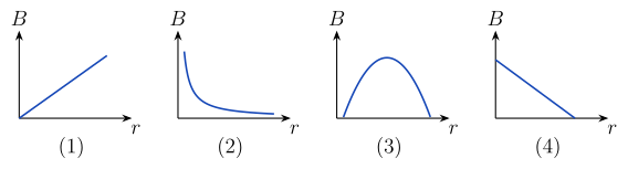 (A) (B) (C) (D)
›Reveal solutionSolution
Ampère's law gives B=μ0I/2πr, i.e. B∝1/r — a rectangular hyperbola.
Step 1 — Apply Ampère's circuital law.
Take a circular Amperian loop of radius r centred on the wire and lying in the plane perpendicular to it. By symmetry B has the same magnitude everywhere on that circle and is tangential to it, so
∮B⋅dl=B(2πr)=μ0Ienc=μ0I
B=2πrμ0I⟹B∝r1
(The direction is given by the right-hand thumb rule, but only the magnitude matters for the graph.)
Step 2 — Shape of B versus r.
- Monotonically decreasing, so any rising graph is out.
- B→∞ as r→0 (the curve hugs the B-axis) and B→0 only as r→∞ — so it approaches the r-axis asymptotically and never crosses it.
- This is a rectangular hyperbola (Br=const), concave up.
Step 3 — Eliminate the distractors.
(A) B∝r is what holds inside a thick current-carrying conductor, not outside it. (D) a straight line falling to zero at a finite r would mean the field vanishes at a finite distance — false. (C) a hump implies a maximum at some r>0 — there is none for an infinitely thin, infinitely long wire.
✓Final answerThe correct option is (B) — the curve falling steeply and flattening asymptotically towards the r-axis (B∝1/r).
ANSWER: B
- COMEDK 2025Set 2025-E1 markMCQQ.A straight wire of mass 250 g and length 2.5 m carries a current of 4 A . It can be suspended in mid air by a uniform horizontal magnetic field of magnitude: (A) 0.145 T (B) 0.245 T (C) 0.625 T (D) 2.245 T
›Reveal solutionSolution
The magnetic force must balance the weight of the wire. Using F=BIL and mg=BIL, we solve for B and get B=0.245 T, so the correct option is (B).
Concept & Intuition
The wire is “suspended in mid air” — that means it’s not falling, so the net vertical force is zero. The only two vertical forces are its weight (downward) and the magnetic force (upward). For a current-carrying wire in a uniform magnetic field, the magnetic force is given by F=BILsinθ. Here the field is horizontal and the wire is straight; to get an upward force, the current direction must be perpendicular to the field. The problem states the field is “uniform horizontal” — so if the wire is horizontal and the current flows perpendicular to the field, the force is vertical. We set that equal to the weight.
Step-by-step
-
Identify the forces
Weight: W=mg, where m=250 g=0.250 kg, g=9.8 m/s2.
Magnetic force: Fm=BILsinθ. For maximum upward force, we take θ=90∘ so sinθ=1. Thus Fm=BIL.
-
Set up the equilibrium condition
Suspended means Fm=W:
BIL=mg
- Solve for B
B=ILmg
Substitute values:
B=(4)(2.5)(0.250)(9.8)
- Calculate Numerator: 0.250×9.8=2.45 Denominator: 4×2.5=10
B=102.45=0.245 T
TipAlways check units: mass in kg, length in m, current in A, g in m/s² — then B comes out in teslas directly.
Watch outA common mistake is forgetting to convert grams to kilograms. Using 250 g directly gives B=245 T, which is absurd — always convert to SI units first.
✓Final answerThe correct option is (B).
ANSWER: B
-
- COMEDK 2024Set 2024-A1 markMCQQ.A long horizontal wire P carries current of 50 A from left to right. It is rigidly fixed. Another fine wire Q is placed directly above and parallel to P. The mass of the wire is 'm' kg and carries a current of 'I' A. The direction of current in Q and position of wire Q from P so that the wire Q remains suspended are (A) Right to left, πmg50Iμ0 (B) Left to right, πmg25Iμ0 (C) Right to left, πmg25Iμ0 (D) Right to left, 4πmgIμ0
›Reveal solutionSolution
The wire Q stays suspended when the upward magnetic force from wire P exactly balances its weight. For parallel currents the force is attractive, so Q’s current must flow opposite to P’s (right to left), and the required separation is πmg25Iμ0. The correct option is (C).
Concept & Intuition
Two parallel current-carrying wires exert a magnetic force on each other: currents in the same direction attract, opposite directions repel. Here wire Q is above P and must be held up against gravity. The only upward force available is the magnetic force from P. Since gravity pulls Q downward, the magnetic force must be upward — that means the wires must attract each other. Attraction occurs when the currents are in the same direction. But careful: P’s current is left to right; if Q’s current is also left to right, they attract, pulling Q downward (toward P). That would add to gravity, not oppose it. So we need the opposite: Q’s current must be right to left, making the currents antiparallel, which gives a repulsive force — pushing Q upward. That repulsion can balance weight.
Now, the magnitude of the magnetic force per unit length between two long parallel wires is
Fmag=2πdμ0I1I2
where d is the separation. For a wire of mass m (presumably per unit length, or total mass — the problem’s phrasing implies m is the mass per unit length, as the force per unit length is what matters for suspension), the weight per unit length is mg. Setting repulsive force upward equal to weight downward gives the equilibrium separation.
Step-by-step solution
-
Identify the force direction
Wire P carries current 50A left to right. For wire Q to be repelled upward, its current must be opposite to P’s — i.e., right to left. This eliminates option (B) (which says left to right).
-
Write the magnetic force per unit length
For two long parallel wires with currents I1 and I2 separated by distance d, the force per unit length is
f=2πdμ0I1I2
Here I1=50A, I2=I (the current in Q). So
f=2πdμ0⋅50⋅I=2πd50μ0I=πd25μ0I
- Set up equilibrium The wire Q is suspended, meaning the net vertical force on it is zero. The upward magnetic force per unit length equals the weight per unit length:
πd25μ0I=mg
(Here m is mass per unit length of Q.)
- Solve for the separation d Rearranging:
d=πmg25μ0I
- Match with options The direction is right to left, and the separation is πmg25Iμ0. This matches option (C).
Watch outA common mistake is to think “same direction attracts, so Q’s current should be same as P’s to pull it up.” But attraction pulls Q toward P — downward, since P is below. For suspension, we need repulsion upward, so currents must be opposite.
TipThe formula F/L=2πdμ0I1I2 is symmetric: swapping currents doesn’t change magnitude, only direction. Always check the direction using the right-hand rule or the “like currents attract” rule.
✓Final answerThe correct option is (C).
ANSWER: C
-
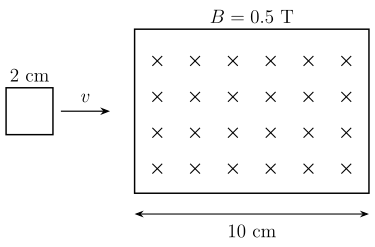
- KCET 2023Set A-31 markMCQQ.A square loop of side 2 cm enters a magnetic field with a constant speed of 2 cm s−1 as shown. The front edge enters the field at t=0s. Which of the following graph correctly depicts the induced emf in the loop ? (Take clockwise direction positive)
 (A) [FIGURE]
(B) [FIGURE]
(C) [FIGURE]
(D) [FIGURE]
(A) [FIGURE]
(B) [FIGURE]
(C) [FIGURE]
(D) [FIGURE]›Reveal solutionSolution
e=Blv is constant while a side cuts field lines, so the emf is a pair of rectangular pulses (entry and exit), of opposite sign, of magnitude 2×10⁻⁴ V and 1 s duration each; Lenz's law fixes the entry pulse as negative for the given sign convention.
Step 1 — Timeline of the motion.
Speed v=2 cm s−1, loop side l=2 cm, field region width =10 cm.
- Entry: the front edge is in the field but the rear edge is not, for the time the loop needs to advance its own length: t=2/2=1 s. So 0≤t≤1 s.
- Fully inside: front edge reaches the far boundary when it has travelled 10 cm, i.e. at t=10/2=5 s. So from t=1 s to t=5 s the loop is entirely inside.
- Exit: takes another 1 s, from t=5 s to t=6 s.
Step 2 — Magnitude of the emf.
While entering or leaving, only one side of length l cuts field lines (the other is outside the field), so
∣e∣=Blv=(0.5)(0.02 m)(0.02 m s−1)=2×10⁻⁴ V.
Because B, l and v are all constant, this emf is constant throughout each 1 s interval — the pulses are rectangular, not triangular. (Equivalently, Φ=Bl(vt) increases linearly, so e=−dΦ/dt is constant.)
Step 3 — When the loop is fully inside (1 s → 5 s).
The flux Φ=Bl2 is now constant (both the entering and leaving edges are inside the same uniform field), so dΦ/dt=0 and e=0.
Step 4 — Sign, by Lenz's law (clockwise taken positive).
- Entering: flux into the page through the loop is increasing. The induced current opposes this, so it must produce flux out of the page inside the loop ⇒ the induced current flows anticlockwise. With clockwise defined as positive, the emf is negative.
- Leaving: the into-page flux is now decreasing; the induced current tries to maintain it, so it flows clockwise ⇒ the emf is positive.
Step 5 — Assemble the graph.
e=−2×10⁻⁴ V (rectangular) for 0<t<1 s; e=0 for 1<t<5 s; e=+2×10⁻⁴ V (rectangular) for 5<t<6 s. That is option (C). (A) and (B) are wrong because they are triangular ramps, and (D) has both pulses with the wrong sign.
✓Final answerThe correct option is (C) — a constant −2×10⁻⁴ V pulse from t=0 to 1 s, zero from 1 to 5 s, and a constant +2×10⁻⁴ V pulse from 5 to 6 s.
ANSWER: C
- COMEDK 2021Set 2021-B1 markMCQQ.A beam of electron is passes through crossed electric and magnetic field, E=9.6×10⁶ N/C and B=2.4 T. If the beam goes un deviated the velocity of electrons is (A) 4.0×10⁶ m/s (B) 9.6×10⁶ m/s (C) 2.0×10⁶ m/s (D) 4.8×10⁶ m/s
›Reveal solutionSolution
Undeviated motion requires qE=qvB, so v=E/B=9.6×106/2.4=4.0×106 m/s.
In crossed electric and magnetic fields, the beam passes straight through when the electric and magnetic forces cancel:
qE=qvB⇒v=BE=2.49.6×106=4.0×10⁶ m/s.
✓Final answerThe correct option is (A) — 4.0×10⁶ m/s
🎓Unlock everything free for 14 days
- ✓Full step-by-step solutions
- ✓Concept-first explanations
- ✓Methods, shortcuts & mistakes
- ✓PYQ mapping + timed mock tests
Full access for 14 days. No credit card required.