Q.If light passes near a massive object, the gravitational interaction causes a bending of the ray. This can be thought of as happening due to a change in the effective refrative index of the medium given by n(r)=1+2GM/rc2 where r is the distance of the point of consideration from the centre of the mass of the massive body, G is the universal gravitational constant, M the mass of the body and c the speed of light in vacuum. Considering a spherical object find the deviation of the ray from the original path as it grazes the object.
🔒You're viewing a preview — the full solution, concept, methods & PYQ mapping are locked.
🔒 Start your 14-day free trial to unlock the full solution →Concept understanding — Refraction at Spherical Surface
Refraction at a Spherical Surface
Imagine you're looking at a fish in a pond. The fish appears closer to the surface than it actually is. That's refraction — light bends when it moves from water to air. Now take that idea and replace the flat water surface with a curved one, like a glass lens or a drop of water. That's refraction at a spherical surface.
The core intuition
When light hits a flat surface (like a glass slab), it bends once and travels straight. But when the surface is curved — part of a sphere — the angle at which light hits changes depending on where on the surface it strikes. A ray hitting near the centre meets the surface almost head-on; a ray hitting near the edge meets it at a steep slant. This variation in incidence angle is what makes spherical surfaces focus or diverge light.
Think of a spherical surface as a tiny piece of a sphere. The centre of that sphere is called the centre of curvature (C). The distance from the surface to C is the radius of curvature (R). The line joining the centre of the surface (the pole, P) to C is the principal axis.
The precise geometry
We need to track what happens to a ray from an object point O on the principal axis. The ray travels in medium 1 (refractive index n1), hits the spherical surface at point A, and enters medium 2 (refractive index n2). The surface has radius R, with centre C.
The key is Snell's law at point A:
n1sini=n2sinr
But i and r are measured from the normal at A. For a spherical surface, the normal at any point is the line joining that point to C. So the normal is AC.
For small angles (paraxial rays — rays close to the axis), sinθ≈θ in radians. This approximation is the backbone of all standard lens and mirror formulas. It lets us replace Snell's law with:
n1i=n2r
Now look at the geometry. Let the object distance from the pole be u (negative by sign convention — object on left), and the image distance be v (positive if image is on the right, in medium 2). The angle the incident ray makes with the axis is α, the refracted ray makes β, and the normal makes θ with the axis.
From the triangles:
- In △OAC: i=α+θ
- In △AIC: r=θ−β (for a convex surface towards the object)
Substitute into Snell's law:
n1(α+θ)=n2(θ−β)
For small angles, α≈POAP≈−uh (since u is negative), β≈vh, and θ≈Rh.
Plugging these in:
n1(−uh+Rh)=n2(Rh−vh)
Cancel h (non-zero) and rearrange:
vn2−un1=Rn2−n1
This is the refraction at a spherical surface formula. It relates object distance u, image distance v, radii R, and the two refractive indices.
Sign convention (crucial for exams)
Use the Cartesian sign convention (the one used in NCERT and most Indian boards):
- Distances measured from the pole P along the principal axis.
- Positive in the direction of incident light (usually left to right).
- Negative opposite to incident light.
- R is positive if the centre of curvature C is on the right (convex surface towards object), negative if C is on the left (concave surface towards object).
The most common mistake is getting the sign of R wrong. Always check: is the centre of curvature on the same side as the incoming light or the opposite side? If opposite, R is positive.
What the formula tells you
- If n2>n1 (going from rarer to denser), the right side Rn2−n1 is positive for a convex surface. This means v is positive — the image forms on the other side (real image). …
Why this formula?
Great — let’s build the Refraction at a Spherical Surface formula from first principles. The goal is to understand why the relation
vn2−un1=Rn2−n1
holds, where:
- n1 = refractive index of the first medium (where the object lies)
- n2 = refractive index of the second medium (where the image lies)
- u = object distance from the pole (sign convention: negative for real object)
- v = image distance from the pole (sign convention: positive for real image on the opposite side)
- R = radius of curvature of the spherical surface (positive if centre of curvature is on the image side)
1. The core idea: Snell’s law at a curved interface
At any point on the spherical surface, the incident ray and refracted ray obey Snell’s law:
n1sini=n2sinr
For small angles (paraxial approximation — rays close to the principal axis), sinθ≈θ (in radians). So:
n1i=n2r
This linearisation is the key that lets us turn geometry into algebra.
2. Geometry of a single ray
Consider a point object O on the principal axis. A ray from O strikes the spherical surface at point P (height h above the axis). Let:
- C = centre of curvature of the spherical surface
- M = pole of the surface (vertex)
- I = image point formed after refraction
Draw the normal at P — it passes through C (since the surface is spherical). The angles:
- i = angle between incident ray OP and the normal PC
- r = angle between refracted ray PI and the normal PC
3. Relating angles to distances (paraxial approximation)
Because h is small compared to u, v, and R:
- Angle between OP and the axis: α≈uh (with sign)
- Angle between PC (normal) and the axis: θ≈Rh
- Angle between PI and the axis: β≈vh
Now, from the geometry of the triangle formed by the ray, the normal, and the axis:
- Incident angle i = angle between OP and the normal = θ−α (if θ>α)
- Refracted angle r = angle between PI and the normal = θ−β
Check the sign convention carefully — the exact relation depends on whether the ray bends toward or away from the normal. For a convex surface (centre on the image side), the standard result is:
i=α+θandr=θ−β
But the difference that matters is:
i−r=α+β
4. Applying Snell’s law
From n1i=n2r, we can write:
n1i=n2(i−(i−r))or directly:
n1i=n2r⟹n1i−n2r=0
But it’s more useful to express r in terms of i and the geometry:
r=i−(α+β)
Substitute into Snell’s law:
n1i=n2[i−(α+β)]
Simplify:
n1i=n2i−n2(α+β)
(n1−n2)i=−n2(α+β)
Now, i≈α+θ (from geometry). For small angles, α≈h/u, β≈h/v, θ≈h/R.
5. Substituting the small-angle approximations
Let’s do it step by step:
(n1−n2)(α+θ)=−n2(α+β)
Replace α, β, θ:
(n1−n2)(uh+Rh)=−n2(uh+vh)
Cancel h (non-zero):
(n1−n2)(u1+R1)=−n2(u1+v1)
6. Rearranging to the standard form
Expand the left side: …
Concept: Refraction at Spherical Surface — The gravitational field acts like a medium with a radially varying refractive index, bending the light ray.
Reasoning:
- For a ray grazing a spherical object of radius R, the refractive index varies only with r. The bending angle δ is given by integrating the gradient of n along the path:
δ=∫−∞∞n1∂x∂ndy
where x is along the radial direction and y along the straight-line path. …
The gravitational bending of light can be treated as refraction through a thin prism of continuously varying refractive index. For a ray grazing a spherical mass, the total deviation is δ=Rc24GM, where R is the object's radius.
The Physics at a Glance
Einstein's general relativity predicts that light bends when passing near a massive object. Remarkably, this effect can be understood using a classical analogy: gravity creates a gradient in the effective refractive index of space. The problem gives us this index as
n(r)=1+rc22GM
where r is the distance from the centre of mass M. As light travels through a medium with a varying refractive index, it bends toward regions of higher n — just like a mirage on a hot road. Here, n increases as r decreases, so light bends toward the massive object.
The key insight: treat the curved path as a series of infinitesimal refractions. For a grazing ray, the total bending angle is twice the Newtonian prediction — a famous result from general relativity.
Step-by-Step Solution
1. Set up the geometry
Consider a ray of light that just grazes the surface of a spherical object of radius R. Let the ray approach from infinity, pass tangent to the surface at closest approach r=R, and recede to infinity. By symmetry, the bending is symmetric about the point of closest approach.
We'll work in a plane containing the ray and the centre of the object. Let x be the coordinate along the original (undeviated) direction, with x=0 at the point of closest approach. The distance from the centre at any point is r=R2+x2.
2. Relate bending to the refractive index gradient
For a medium with n(r) varying slowly, the ray bends according to Snell's law applied locally. A standard result from geometrical optics: the curvature of a ray in a medium with gradient ∇n is given by
dsdθ=n1drdnsinϕ
where θ is the angle the ray makes with some reference, s is the path length, and ϕ is the angle between the ray direction and the gradient direction. For our radial gradient, ϕ is the angle between the ray and the radial line.
For a ray passing at distance r from centre, the local bending rate is
dxdδ=n(r)1drdnrR
where δ is the cumulative deviation angle from the original straight path.
3. Compute the gradient
From n(r)=1+rc22GM, we get
drdn=−r2c22GM
The negative sign means n decreases as r increases — the gradient points inward, so light bends toward the object.
4. Set up the integral for total deviation
For a grazing ray, the total deviation δ is the integral of all infinitesimal bendings along the path. Since n≈1 (the correction is tiny — for the Sun, 2GM/Rc2≈4×10−6), we can approximate n≈1 in the denominator.
The geometry gives sinϕ=R/r (the component of the gradient perpendicular to the ray). So …
Method: Total Deviation From a Radially-Varying Refractive Index (Grazing-Ray Integration)
Use this method for problems where a ray passes near (grazing) a spherically symmetric region with a refractive index that depends only on distance r from the centre, and you need the total accumulated deviation over the whole path — not just a local rate, as for a short horizontal segment.
Steps
Step 1: Set up coordinates along and perpendicular to the undeviated path
Let x be the coordinate along the ray's original straight-line direction, with x=0 at the point of closest approach (here, at the surface, distance R from the centre). The distance from the centre at any point along the path is then r=R2+x2.
Step 2: Write the local bending rate using the radial gradient of n
Differentiate the given n(r) to get dn/dr. The component of this gradient perpendicular to the ray (the part that actually bends it) involves the geometric factor sinϕ=R/r (from the same right triangle used in Step 1), giving a local bending rate
dxdδ=n1drdn⋅rR
Since the index correction is tiny, approximate n≈1 in this expression.
Step 3: Substitute r=R2+x2 and set up the full integral
Express dxdδ purely in terms of x (and constants R, and whatever parameters define n(r)), then integrate over the entire path, x from −∞ to ∞ (using symmetry to write it as twice the integral from 0 to ∞ where convenient).
Step 4: Evaluate the integral with a standard substitution …
Showing the 12 most recent of 18 on this concept.
- COMEDK 2025Set 2025-A1 markMCQQ.A beam of light parallel to the principal axis of a concave and convex lens, first passes through the concave lens of focal length 0.5 m and then through the convex lens of focal length 1.75 m . If the lenses are placed 1.25 apart, which of the given statement is true? (A) The emergent beam will focus at 1.75 m on the principal axis. (B) The emergent beam will focus at 1.25 m on the principal axis. (C) The emergent beam will pass parallel to the principal axis. (D) The emergent beam will focus at 0.75 m on the principal axis.
›Reveal solutionSolution
The parallel beam diverges through the concave lens as if from its focus; that virtual image sits exactly at the focus of the convex lens, so the emergent beam leaves parallel to the axis — option (C).
Concave lens (f1=−0.5 m): a beam parallel to the axis forms a virtual image at its focal point,
v1=f1=−0.5 m,
i.e. 0.5 m in front of the concave lens (on the incoming side).
Convex lens (f2=+1.75 m), placed 1.25 m beyond the concave lens: the virtual image acts as the object. Its distance from the convex lens is
u=1.25+0.5=1.75 m. …
- COMEDK 2025Set 2025-E1 markMCQQ.A beam of incident parallel light falls on a diverging lens of focal length 20 cm in magnitude. If a converging lens of focal length 15 cm in magnitude is placed at a distance of 10 cm to the right of the diverging lens on the other side, then, the final image formed is: (A) Virtual and is at a distance of 30 cm to the right of the converging lens. (B) Virtual and is at a distance of 40 cm to the right of the diverging lens. (C) Real and is at a distance of 30 cm to the right of the converging lens. (D) Real and is at a distance of 40 cm to the right of the converging lens.
›Reveal solutionSolution
The problem is a two-lens system where parallel light first hits a diverging lens, creating a virtual object for the converging lens. Using the lens formula step by step, the final image is real and located 30 cm to the right of the converging lens, matching option (C).
Concept & Intuition
When parallel light (rays from infinity) enters a diverging lens, the lens makes them appear to come from its virtual focus. That virtual image then acts as an object for the second lens. The trick is that if this object lies behind the second lens (on the opposite side from where light is traveling), it’s a virtual object for that lens — and virtual objects can produce real images. We apply the lens formula carefully, keeping sign conventions consistent.
- First lens (diverging, focal length f1=−20 cm) Parallel light means object distance u1=∞. Lens formula: v11−u11=f11. With u1=∞, u11=0, so
v11=f11=−201⇒v1=−20 cm.
The negative sign means the image is 20 cm to the left of the diverging lens (virtual, on the same side as the incoming light).
-
Position relative to the second lens
The converging lens is 10 cm to the right of the diverging lens.
So the first image is 20 cm left of the diverging lens, which is 20+10=30 cm left of the converging lens.
For the converging lens, object distance u2=−30 cm (negative because the object is on the opposite side from the incoming light — a virtual object).
-
Second lens (converging, focal length f2=+15 cm)
Use the lens formula again:
v21−u21=f21.
Substitute u2=−30 cm, f2=+15 cm:
- COMEDK 2025Set 2025-E1 markMCQQ.An object of height h is placed midway between f and 2f in front of a biconvex lens. A real inverted image is captured on a screen placed a little beyond 2 f on the other side of the lens. If the whole arrangement is immersed in water without disturbing the object, lens and the screen positions, then the new image formed will be (A) Magnified virtual erect image on the same side of the lens where the object is placed (B) Magnified real inverted image on the same side of the lens where the object is placed (C) Diminished real inverted image on the other side of the lens between f and 2f (D) Magnified real inverted image on the other side of the lens beyond 2f
›Reveal solutionSolution
In air the object at 1.5f gives a real, inverted, magnified image beyond 2f. Immersing the glass lens in water makes its focal length roughly 4 times larger, so the fixed object now lies inside the new focal length — producing a magnified, virtual, erect image on the same side as the object — option (A).
Concept
The focal length of a biconvex lens depends on the surrounding medium through the lens-maker relation
f1=(nmediumnlens−1)(R11−R21).
Going from air to water sharply reduces the effective refractive-index contrast, so f increases.
Step-by-step solution
-
Original situation (in air). Object is midway between f and 2f, i.e. at u=1.5f. Since f<u<2f, the image is real, inverted and magnified, formed just beyond 2f — consistent with the given screen position.
-
Focal length in water. Taking nglass=1.5 and nwater=1.33,
fairfwater=nwng−1ng−1=1.331.5−10.5≈0.1280.5≈3.9.
So the new focal length is fwater≈3.9f. …
-
- COMEDK 2025Set 2025-E1 markMCQQ.A plano-convex lens made of refractive index 1.5 and having radius of curvature R=4 cm fits exactly into a planoconcave lens made of refractive index 1.3 and having the same radius of curvature R=4 cm such that their plane surfaces are parallel to each other. The focal length of the combination is : (A) 5 cm (B) 50 cm (C) 2 cm (D) 20 cm
›Reveal solutionSolution
The combination behaves as a single lens whose net power is the sum of the individual lens powers. Using the lens maker’s formula for each lens and adding them gives a focal length of 20 cm, so the correct option is (D).
We have two lenses placed in contact: a plano-convex lens (refractive index 1.5) and a plano-concave lens (refractive index 1.3), both with the same radius of curvature R=4cm. Their plane surfaces are parallel and facing each other. The key is to treat the combination as two thin lenses in contact, so the net power is simply the algebraic sum of their individual powers. The lens maker’s formula gives the power of each lens from its geometry and refractive index.
- Lens maker’s formula For a thin lens in air, the power P (in diopters if R is in meters) is
P=f1=(n−1)(R11−R21)
where R1 and R2 are the radii of curvature of the two surfaces, with sign convention: convex toward the incident light is positive, concave is negative.
- First lens: plano-convex (refractive index n1=1.5)
- One surface is plane: R1=∞ (radius infinite, so 1/R1=0).
- The other surface is convex toward the incident light (say light comes from the plane side first, but the sign is consistent). Typically, for a plano-convex lens, the convex surface has R2=−R if the plane is on the incident side? Let’s be careful: We can choose the orientation. Since the two lenses fit together, their curved surfaces are in contact. For the plano-convex lens, the curved surface is convex and faces the other lens. If we take light incident from the plane side, then the first surface is plane (R1=∞) and the second surface is convex toward the light, so R2=+R=+4cm (convex surface has positive radius when the center of curvature is on the outgoing side). Then
P1=(1.5−1)(∞1−41)=0.5×(0−41)=−0.125cm−1
That gives a negative power — but a plano-convex lens is converging! This sign error is a classic pitfall.Watch outThe sign convention must be applied consistently: For a lens in air, the standard Cartesian sign convention is:
- Radius is positive if the center of curvature lies to the right of the surface (for light traveling left to right).
- For a plano-convex lens with the plane side facing the incident light, the second surface is convex, so its center of curvature is to the right → R2=+R. But then the formula gives negative power? That can’t be right. Actually, the correct form of the lens maker’s formula is f1=(n−1)(R11−R21) with the sign convention: R positive if the surface is convex toward the incident light. For a plano-convex lens with the plane side first, the first surface is plane (R1=∞), the second surface is convex toward the incident light? No — the light hits the plane surface first, then the convex surface. The convex surface is curved away from the incident light (its center is on the far side), so it is concave toward the incident light. Therefore R2 should be negative. Let’s redo properly.
- Correct sign convention for lens maker’s formula
Use the standard: For each surface, R is positive if the center of curvature lies on the side of the outgoing light (i.e., the surface is convex toward the incident light).
- For the plano-convex lens: Light enters from the plane side.
- First surface (plane): R1=∞.
- Second surface (curved): The center of curvature is on the outgoing side (to the right), so the surface is convex toward the incident light? Actually, if light is going left to right, and the convex surface bulges to the right, then the incident light sees a convex surface — yes, because the surface curves away from the incoming light. So R2=+R=+4cm. Then
- For the plano-convex lens: Light enters from the plane side.
f11=(1.5−1)(∞1−+41)=0.5×(0−0.25)=−0.125cm−1
This gives a negative focal length, meaning diverging — but a plano-convex lens is converging. The error: The formula is actuallyf1=(n−1)(R11−R21)
where $ R_1 $ is the radius of the first surface (incident side) and $ R_2 $ of the second surface (exit side), with the sign: positive if the center of curvature is on the *right* (for light traveling left to right). For a plano-convex lens with the plane side left, the first surface is plane ($ R_1 = \infty $), the second surface is convex, so its center is to the right → $ R_2 = +4 $. Then the formula gives negative power. That suggests the formula is actually $$ \frac{1}{f} = (n-1)\left( \frac{1}{R_1} - \frac{1}{R_2} \right) $$ … - COMEDK 2025Set 2025-M1 markMCQQ.A symmetric double convex lens is cut into two equal parts by a plane perpendicular to the principal axis. If the power of the original lens is 4D, the difference between the powers of the original lens and the cut lens is (A) zero (B) 3D (C) D (D) 2D
›Reveal solutionSolution
When a symmetric double convex lens is cut perpendicular to the principal axis, each half becomes a plano-convex lens with the same radius of curvature on the curved side. The power of each half is half the original power, so the difference between the original power (4D) and the power of one cut lens (2D) is 2D.
Concept and Intuition
The power of a lens depends on its curvature and the refractive index of the material. For a symmetric double convex lens, both surfaces have the same radius of curvature R. The lens maker’s formula gives the power as P=(n−1)(R11−R21). When you cut the lens perpendicular to the principal axis, you split it into two identical plano-convex lenses. Each half has one flat surface (radius of curvature ∞) and one curved surface with the original radius R. The flat surface contributes zero power, so the power of each half is exactly half the original power. The question asks for the difference between the original power and the power of one cut lens.
Step-by-step solution
- Original lens power For a symmetric double convex lens, both surfaces have the same radius of curvature R but opposite signs (convex toward the incoming light). Using the lens maker’s formula:
Poriginal=(n−1)(R1−−R1)=(n−1)(R2)
Given Poriginal=4D, we have:
(n−1)R2=4⇒(n−1)R1=2
- Power of one cut lens After cutting, each half is a plano-convex lens. The flat side has R1=∞ (so 1/R1=0), and the curved side has R2=R (positive if the convex side faces the incoming light). The power is:
Phalf=(n−1)(∞1−R1)=(n−1)(0−R1)=−(n−1)R1
The negative sign just indicates the orientation; the magnitude of the power is:
- COMEDK 2025Set 2025-M1 markMCQQ.One surface of a lens is convex and the other is concave. If the radii of curvatures are R and r respectively, the lens will be convex if (A) R>r (B) R<r (C) R=r1 (D) R=r
›Reveal solutionSolution
The lens is convex when the net curvature is positive; for a convex-concave lens, this happens when the convex side has a smaller radius of curvature than the concave side, i.e., R<r. The correct option is (B).
The key idea is the lens maker’s formula and the sign convention for radii of curvature. A lens is convex (converging) if its net focal length is positive. For a lens with one convex and one concave surface, the sign of the focal length depends on which radius is larger.
Why this works:
In the lens maker’s formula, f1=(n−1)(R11−R21), the sign of each radius is taken as positive if the surface is convex toward the incoming light, and negative if concave. For a convex-concave lens, the convex side has R1>0 and the concave side has R2<0 (if light enters from the convex side). The term R11−R21 becomes R1−(−r)1=R1+r1. For the lens to be convex (converging), we need this sum to be positive — which it always is — but the thickness and shape matter: a convex-concave lens is actually convex only if the convex surface is more curved (smaller radius) than the concave surface.
Let’s work through it step by step.
-
Set up the sign convention.
Assume light enters from the convex side. Then the first surface (convex) has radius R1=+R. The second surface (concave) has radius R2=−r (since the center of curvature lies on the opposite side of the incoming light).
-
Apply the lens maker’s formula.
For a thin lens in air:
f1=(n−1)(R11−R21)
Substitute R1=R, R2=−r:
f1=(n−1)(R1−−r1)=(n−1)(R1+r1)
-
Interpret the sign of f.
Since n>1 and both R and r are positive lengths, R1+r1>0, so f>0. This suggests the lens is always converging — but that’s misleading. The formula assumes the lens is thin and the radii are measured from the same direction. In reality, a convex-concave lens can be either converging or diverging depending on which surface is more curved.
-
Think physically: which side bulges more? …
-
- KCET 2024Set D-21 markMCQQ.The final image formed by an astronomical telescope is (A) real, erect and diminished (B) virtual, inverted and diminished (C) real, inverted and magnified (D) virtual, inverted and magnified
›Reveal solutionSolution
Objective ⇒ real inverted image; eyepiece used as a magnifier ⇒ that image is re-imaged as a virtual, magnified image, still inverted with respect to the object.
Step 1 — Stage 1: the objective
The object (a star, a planet) is effectively at infinity. The objective is a converging lens of large focal length fo, so it forms a real, inverted, diminished image A′B′ in its focal plane — i.e. at a distance fo behind the objective.
This intermediate image is real, and that is essential: it becomes the object for the eyepiece.
Step 2 — Stage 2: the eyepiece
The eyepiece is a converging lens of short focal length fe, placed so that the intermediate image A′B′ lies at or just inside its first focal point. A converging lens with an object inside its focal length behaves as a simple microscope (magnifying glass), and such a lens always produces a virtual, erect, magnified image of its own object.
- "Erect with respect to A′B′" — but A′B′ was itself inverted with respect to the original object.
- Hence the final image is inverted with respect to the original object.
Step 3 — Why "magnified"
For a telescope, magnification means angular magnification, not linear size. In normal adjustment,
m=−fefo …
- COMEDK 2024Set 2024-A1 markMCQQ.An object is placed at a distance of 12 cm from a convex lens on its principal axis and a virtual image of certain size is formed. If the object is moved 4 cm away from the lens, a real image of the same size as that of the virtual image is formed. The focal length of the lens in cm is (A) 12 (B) 14 (C) 18 (D) 16
›Reveal solutionSolution
The problem uses the lens formula and magnification to relate two object positions that produce images of equal size (one virtual, one real). Solving the resulting equations gives the focal length as 16 cm.
The key insight is that the magnitude of magnification is the same in both cases, but the sign differs because one image is virtual (upright, positive magnification) and the other is real (inverted, negative magnification). The lens formula f1=v1−u1 (with sign convention: object distance u is negative for real objects) lets us express image distances in terms of u and f, then equate the absolute magnifications.
- Set up the sign convention and first case. For a convex lens, we use the Cartesian sign convention: object distance u is negative. Let the focal length be f (positive for convex). First object distance: u1=−12 cm. The image is virtual, so v1 is negative. Lens formula:
f1=v11−u11=v11−−121=v11+121.
Magnification m1=u1v1=−12v1. Since the image is virtual and upright, m1>0, so v1 is negative (consistent). The size (absolute value) is ∣m1∣=12∣v1∣.
- Second case. Object moved 4 cm away: u2=−(12+4)=−16 cm. Now a real image is formed, so v2>0. Lens formula:
f1=v21−−161=v21+161.
Magnification m2=u2v2=−16v2, which is negative (real, inverted). The absolute size is ∣m2∣=16v2.
- Equal image size condition. The problem says the size (absolute value) is the same:
∣m1∣=∣m2∣⇒12∣v1∣=16v2.
Since v1 is negative, ∣v1∣=−v1. So:
12−v1=16v2⇒v2=−34v1.(1)
- Use the lens formula for both cases. From case 1:
f1=v11+121.(2)
From case 2:
f1=v21+161.(3)
Equate (2) and (3):
v11+121=v21+161.
Substitute v2 from (1):
v11+121=−34v11+161=−4v13+161. …
- COMEDK 2024Set 2024-A1 markMCQQ.To a fish under water, viewing obliquely, a fisherman standing on the bank of a lake looks (A) Same height as he actually is (B) Shorter than what he actually is (C) Taller than what he actually is (D) Taller or shorter depending on the refractive index of water
›Reveal solutionSolution
When light travels from air (rarer) into water (denser), the apparent position of an object is shifted upward. For a fisherman on the bank viewed from underwater, his image appears taller than his actual height because the rays from his feet and head bend differently, stretching the perceived vertical size.
The key concept here is apparent depth and apparent height due to refraction. When you view an object from a denser medium (water) into a rarer medium (air), the light rays bend away from the normal as they enter the water. This makes the object appear farther away and larger in the vertical direction. The classic example is a stick partly immersed in water appearing bent — but here, the observer is underwater, looking up at the fisherman.
Let’s work through the reasoning step by step.
-
Set up the geometry
Imagine the fisherman standing on the bank, with his feet at the water’s edge and his head above. An underwater fish looks obliquely upward at him. Light from the fisherman’s head and feet travels from air (refractive index n1≈1) into water (refractive index n2≈1.33). At the water surface, the rays bend toward the normal (since they go from rarer to denser medium).
-
Apply Snell’s law for a small angle approximation
For a ray coming from a point on the fisherman at height h above the water, the angle of incidence in air is i and the angle of refraction in water is r, with n1sini=n2sinr. For small angles (oblique but not extreme), sinθ≈tanθ≈θ. The apparent height h′ as seen from underwater is given by the formula for apparent depth in reverse:
Apparent height=n1n2×real height
Since n2>n1, the apparent height is larger than the real height.
- Why this formula works Consider a point at real height h above the water. The ray from that point to the fish’s eye makes an angle i in air and r in water. The apparent position is where the backward extension of the refracted ray in water meets the vertical line through the object. Using geometry and Snell’s law, the apparent height h′ satisfies
h′tanr=htani
For small angles, tani≈i and tanr≈r, and Snell’s law gives i=n2r/n1. Substituting yields
h′⋅r=h⋅n1n2r⇒h′=n1n2h
So the fisherman appears taller by a factor of about 1.33.
- Consider the whole body …
-
- COMEDK 2024Set 2024-A1 markMCQQ.In a container of height 21 cm, certain transparent liquid is taken to a height of 12 cm. When seen from above, it appears half filled. The refractive index of the liquid is (A) 67 (B) 45 (C) 34 (D) 23
›Reveal solutionSolution
The liquid's real depth of 12 cm appears reduced to the 9 cm empty column above it, so n=apparent depthreal depth=912=34 — option (C).
The container is 21 cm tall with liquid to a real depth of 12 cm, leaving a 21−12=9 cm air column above. Viewing from above raises the apparent bottom, so the liquid's apparent depth is
dapp=ndreal. …
- COMEDK 2024Set 2024-E1 markMCQQ.Figure below shows a lens of refractive index, μ=1.4. C1 and C2 are the centres of curvature of the two faces of the lens of radii of curvature 4 cm and 8 cm respectively. The lens behaves as a (A) diverging lens of focal length 20 cm (B) converging lens of focal length 20 cm (C) converging lens of focal length 12 cm (D) diverging lens of focal length 12 cm
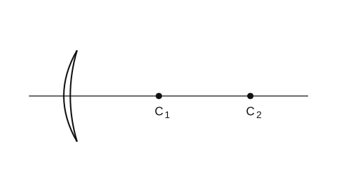
›Reveal solutionSolution
The lens is a meniscus with both centres of curvature on the same side; using the lens maker’s formula with the correct sign convention shows it is a converging lens of focal length 20 cm. The correct option is (B).
Concept & Intuition
The lens maker’s formula relates the focal length of a thin lens to its refractive index and the radii of curvature of its two surfaces. The crucial step is assigning the correct sign to each radius according to the Cartesian sign convention: distances measured from the lens toward the incident light are positive, and distances measured opposite to the incident light are negative.
Here the incident light comes from the left. Both centres of curvature C1 and C2 lie to the right of the lens. That means:
- For the left surface (first surface the light hits), the centre of curvature is on the opposite side from the incident light → radius is negative.
- For the right surface, the centre of curvature is also on the opposite side from the incident light → radius is also negative.
A negative radius for a surface means it is concave toward the incident light. So both surfaces are concave from the left side, making the lens a meniscus shape that is thicker at the centre than at the edges? Actually, if both surfaces curve away from the incident light, the lens is thinner in the middle — that would be a diverging lens in air. But wait: the refractive index is 1.4 (greater than air), and the shape is a meniscus with both centres on the same side. The sign of the focal length depends on the combination. Let’s compute carefully.
Step-by-step solution
-
Identify the radii with sign
- Left surface: radius R1=−4 cm (centre C1 is to the right, opposite to incident light).
- Right surface: radius R2=−8 cm (centre C2 is also to the right).
-
Lens maker’s formula (thin lens in air):
f1=(μ−1)(R11−R21)
Here μ=1.4, so μ−1=0.4.
- Substitute the signed radii:
f1=0.4(−41−−81)
Simplify inside parentheses:
−41−−81=−41+81=−82+81=−81
- Compute focal length:
f1=0.4×(−81)=−80.4=−201
Hence
f=−20 cm
A negative focal length means the lens is diverging. But wait — the options include a diverging lens of focal length 20 cm (option A) and a converging lens of 20 cm (option B). Our calculation gives f=−20 cm, which is diverging. However, we must double-check the sign convention: many textbooks define R positive if the centre of curvature is on the same side as the outgoing light. Let’s re-evaluate with the standard convention used in most Indian exams (the “new Cartesian” convention).
Watch outA common pitfall: mixing sign conventions. In the standard lens maker’s formula used in many textbooks (especially for competitive exams), the sign convention is:
- For a convex surface (bulging toward the incident light), R is positive.
- For a concave surface (curving away from incident light), R is negative. Here, both surfaces curve away from the incident light (since centres are on the right), so both R1 and R2 are negative. That is what we used. But the result f=−20 cm suggests a diverging lens. Yet the figure shows a meniscus that is thicker at the centre? Let’s check the shape: if both centres are on the right, the left surface is convex toward the left? Actually, if the centre is to the right, the surface bulges toward the left — that is convex to the left, meaning it is converging for the left surface. Wait, we need to be careful:
- A surface with centre on the right: the surface curves toward the left (like a dome facing left). That is a convex surface for light coming from the left.
- So the left surface is convex (bulging toward incident light) → R1 should be positive in the standard convention.
- The right surface also has its centre on the right, so it curves away from the incident light (concave) → R2 is negative.
Let’s correct the sign assignment: …
- KCET 2023Set A-31 markMCQQ.An equiconvex lens made of glass of refractive index 23 has focal length f in air. It is completely immersed in water of refractive index 34. The percentage change in the focal length is (A) 300% decrease (B) 400% decrease (C) 300% increase (D) 400% increase
›Reveal solutionSolution
Apply the lens-maker's formula twice — once with n=3/2 in air, once with the relative index nrel=(3/2)/(4/3) in water — and compare.
1. The concept — the lens-maker's formula.
A lens focuses light because of refraction at its two surfaces. The focal length depends on the index of the lens relative to its surroundings:
f1=(nmediumnlens−1)(R11−R21)
That relative index is the whole point of this question: put the lens in a medium closer to its own index, and it bends light less.
2. Geometry of an equiconvex lens.
For an equiconvex lens, R1=+R and R2=−R, so
R11−R21=R1−(−R1)=R2
3. In air (nmedium=1).
f1=(23−1)R2=21⋅R2=R1⟹f=R
4. In water (nmedium=4/3).
The relative index is
nrel=4/33/2=23×43=89 …
🎓Unlock everything free for 14 days
- ✓Full step-by-step solutions
- ✓Concept-first explanations
- ✓Methods, shortcuts & mistakes
- ✓PYQ mapping + timed mock tests
Full access for 14 days. No credit card required.