Q.A 5V battery in series with a 25Ω resistor is connected between a left node-rail and a right node-rail, driving three parallel branches between the two rails (the battery branch carries the current I1). Taking the left rail as the higher-potential side: the top branch (I4) has a diode oriented to conduct from the left rail to the right rail in series with a 125Ω resistor; the middle branch (I3) has a diode oriented the OPPOSITE way (blocking current from left to right) in series with a 125Ω resistor; the third branch (I2) has a diode oriented to conduct from left to right in series with a 125Ω resistor. Each diode has a forward-bias resistance of 25Ω and infinite resistance in reverse bias. Find the values of the currents I1, I2, I3 and I4.
🔒You're viewing a preview — the full solution, concept, methods & PYQ mapping are locked.
🔒 Start your 14-day free trial to unlock the full solution →Concept understanding — Diode Resistance Calculation
Diode Resistance: What Does It Even Mean?
Think of a diode as a one-way valve for electricity. When you push current through it in the forward direction, the diode doesn't just let everything through freely — it resists the flow, just like any other component. But here's the twist: that resistance isn't a fixed number like a resistor's 100 Ω. It changes depending on how much voltage you apply.
Why? Because a diode is a semiconductor device. Its current-voltage relationship follows the Shockley equation:
I=IS(eV/ηVT−1)
where IS is the reverse saturation current, V is the applied voltage, η is the ideality factor (usually 1 for silicon), and VT≈26 mV at room temperature.
This exponential curve means that a tiny change in voltage can cause a huge change in current. So the "resistance" you measure depends entirely on where you are on that curve.
Two Kinds of Diode Resistance
Because the I-V curve is nonlinear, we define two different resistances — each useful in different situations.
1. Static (DC) Resistance
This is the simplest idea: just apply Ohm's law using the total voltage and total current at a given operating point.
RDC=IV
For example, if a diode has 0.7 V across it and 10 mA flowing through it, its DC resistance is:
RDC=0.010.7=70 Ω
Static resistance tells you the average opposition to current at that specific point. It's useful for power calculations (P=I2RDC) but not for small signal analysis.
2. Dynamic (AC) Resistance
This is the more important one for circuit design. It tells you how the diode responds to small changes in voltage around a fixed operating point.
Mathematically, dynamic resistance is the slope of the I-V curve at that point:
rd=dIdV
For a forward-biased diode obeying the Shockley equation, we can derive a clean formula. Starting from:
I=ISeV/ηVT
(ignoring the -1, which is negligible in forward bias)
Differentiate:
dVdI=ηVTI
Therefore:
rd=dIdV=IηVT
rd=IηVT
At room temperature with η=1 and VT=26 mV:
rd=I26 mV
So if the diode current is 10 mA, rd=2.6 Ω — much smaller than the 70 Ω DC resistance.
Dynamic resistance is not a physical resistor inside the diode. It's a small-signal model parameter. You cannot use it with DC voltages or large signals — only for tiny variations around the operating point.
When Do You Use Each?
| Situation | Use |
|---|---|
| Finding DC power dissipation | RDC |
| Designing a biasing circuit | RDC |
| Analyzing small-signal amplifier response | rd |
| Calculating voltage regulation in a Zener diode | rd (called Zener impedance) |
A Quick Example to Tie It Together
A silicon diode (η=1) is forward biased with V=0.7 V and carries I=20 mA.
Static resistance: …
Why this formula?
Diode Resistance: Why It Changes with Operating Point
A diode is not a linear resistor. Its current-voltage relationship follows the Shockley equation:
I=IS(eV/ηVT−1)
where IS is the reverse saturation current, η is the ideality factor (typically 1–2), and VT=kT/q≈26mV at room temperature.
Because the I–V curve is exponential, the diode's resistance depends entirely on where you are on that curve. There are two distinct resistances we care about: DC resistance (static) and AC resistance (dynamic).
DC Resistance (Static Resistance)
Definition: The ratio of the DC voltage across the diode to the DC current through it at a given operating point.
RDC=IV
Why this formula? It's simply Ohm's law applied to the DC values. If you put 0.7 V across a diode and get 10 mA through it, the DC resistance is 0.7/0.01=70Ω. But this number is misleading — it doesn't tell you how the diode responds to a small change in voltage.
DC resistance is rarely useful in circuit analysis because diodes are never operated as fixed resistors. It's just a snapshot at one point.
AC Resistance (Dynamic Resistance)
Definition: The slope of the I–V curve at a given operating point — i.e., the ratio of a small change in voltage to the resulting small change in current.
rd=dIdV
Why this formula? For small signals (like an AC voltage superimposed on a DC bias), the diode behaves approximately linearly around that bias point. The dynamic resistance is the local slope of the I–V curve.
Now let's derive the actual expression.
Derivation of rd=IηVT
Start from the Shockley equation. For forward bias where V≫VT, the −1 term is negligible:
I≈ISeV/ηVT
Take the derivative with respect to V:
dVdI=IS⋅ηVT1⋅eV/ηVT=ηVTI
The dynamic resistance is the reciprocal:
rd=dIdV=IηVT
rd=IηVT
Key insight: The dynamic resistance is inversely proportional to the DC current I. At higher currents, the diode's I–V curve is steeper, so a small voltage change produces a larger current change — meaning lower resistance.
Why This Matters …
The middle diode is reverse biased, so its branch carries no current: I3=0. Each of the other two branches presents 150Ω (125Ω resistor + 25Ω forward diode); with the 25Ω battery resistor, the 5V source drives I1=0.05A, which splits equally to give I2=I4=0.025A.
Which branches conduct
The 5V battery (with its series 25Ω) drives current out of the left rail. The diodes decide the paths:
- Top branch (I4) and third branch (I2): diodes forward biased ⇒ conduct.
- Middle branch (I3): diode reverse biased ⇒ open, so I3=0.
Branch resistance
Each conducting branch = resistor + forward diode:
Rbranch=125+25=150Ω.
The two conducting branches are in parallel:
Rp=150+150150×150=75Ω.
Total current from the battery …
Method: Reducing a Diode Network to Resistances, Branch by Branch
Step 1 -- Determine which branches conduct.
Compare each diode's orientation to the direction current is driven by the 5 V source (left rail to right rail). The top and third branches have diodes oriented to conduct in that direction -- they carry current. The middle branch's diode is oriented the opposite way -- it is reverse-biased and carries no current at all: I3=0.
Step 2 -- Find the resistance of each conducting branch.
Each conducting branch is a 125Ω resistor in series with a forward-biased diode (25Ω):
Rbranch=125+25=150Ω.
Step 3 -- Combine the two conducting branches, which are in parallel.
Rp=150+150150×150=75Ω.
Step 4 -- Add the battery's own series resistance to get the total circuit resistance, then find the total current by Ohm's law. …
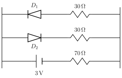
- KCET 2025Set D-41 markMCQQ.The circuit shown in figure contains two ideal diodes D1 and D2. If a cell of emf 3V and negligible internal resistance is connected as shown, then the current through 70Ω resistance, (in ampere) is
 (A) 0.01
(B) 0.02
(C) 0.03
(D) 0
(A) 0.01
(B) 0.02
(C) 0.03
(D) 0›Reveal solutionSolution
The two diodes face opposite ways, so only one 30Ω branch conducts; the circuit is then simply 30Ω+70Ω in series with the 3 V cell.
Step 1 — What an ideal diode does.
An ideal diode is a perfect one-way switch:
- Forward biased (conventional current entering the anode, i.e. flowing in the direction the triangle points): resistance =0 — behaves as a plain wire.
- Reverse biased: resistance =∞ — behaves as an open circuit (a break in the wire).
Step 2 — Read the circuit.
There are three branches between the left rail and the right rail:
- Top: D1 in series with 30Ω. D1 points left, so it can pass conventional current only right → left.
- Middle: D2 in series with 30Ω. D2 points right, so it can pass current only left → right.
- Bottom: the 3 V cell in series with the 70Ω resistor.
The two diode branches are in parallel with each other, and that parallel combination is in series with the cell and the 70Ω resistor around the loop.
Step 3 — The key observation: exactly one diode conducts.
The cell drives current one way round the loop, so the current in the parallel section must flow either left→right or right→left. Because D1 and D2 are wired in opposite senses:
- If the current in that section is left → right, then D2 is forward biased (conducts) and D1 is reverse biased (blocks).
- If it is right → left, then D1 conducts and D2 blocks.
Either way, exactly one of the two 30Ω branches carries current and the other is an open circuit. The two 30Ω resistors are therefore NOT in parallel — that is the trap the question is built around. (If you wrongly parallel them you get 15+70=85Ω and I≈0.035A, which matches no option.)
Step 4 — Reduce the circuit.
The conducting diode is an ideal short (0 Ω), so the whole loop is just: …
- KCET 2023Set A-31 markMCQQ.The resistance of a carbon resistor is 4.7 kΩ±5%. The colour of the third band is (A) red (B) violet (C) orange (D) gold
›Reveal solutionSolution
Write 4.7 kΩ as 47×102 Ω; the third band is the multiplier 102, which is red.
Step 1 — The colour code
For a four-band carbon resistor:
- Band 1 → first significant digit
- Band 2 → second significant digit
- Band 3 → multiplier (power of ten)
- Band 4 → tolerance (gold =±5%, silver =±10%)
Digit/multiplier colours: Black 0, Brown 1, Red 2, Orange 3, Yellow 4, Green 5, Blue 6, Violet 7, Grey 8, White 9.
Step 2 — Express the value in "two digits × multiplier" form
R=4.7 kΩ=4700 Ω=47×102 Ω
Step 3 — Read off the bands
- Band 1 = digit 4 → yellow
- Band 2 = digit 7 → violet
- Band 3 = multiplier 102 → the colour for 2 → red …
- KCET 2023Set A-31 markMCQQ.The four bands of a colour coded resistor are of the colours gray, red, gold and gold. The value of the resistance of the resistor is (A) 82 Ω±10% (B) 8.2 Ω±5% (C) 82 Ω±5% (D) 5.2 Ω±5%
›Reveal solutionSolution
Read the four bands as (digit)(digit)(multiplier)(tolerance): gray 8, red 2, gold ×10−1, gold ±5%.
Step 1 — The colour code.
In a four-band resistor:
- Band 1 = first significant digit
- Band 2 = second significant digit
- Band 3 = decimal multiplier
- Band 4 = tolerance
The digit values (B B ROY of Great Britain has a Very Good Wife): Black 0, Brown 1, Red 2, Orange 3, Yellow 4, Green 5, Blue 6, Violet 7, Gray 8, White 9.
Step 2 — Read the bands.
Band Colour Meaning 1 Gray 8 2 Red 2 3 Gold multiplier ×10−1 4 Gold tolerance ±5% - COMEDK 2023Set 2023-E1 markMCQQ.The reverse current in the semiconductor diode changes from 20μA to 40μA when the reverse potential is changed from 10 V to 15 V, then the reverse resistance of the junction diode will be : (A) 250 kΩ (B) 400Ω (C) 400 kΩ (D) 250Ω
›Reveal solutionSolution
The reverse resistance is ΔV/ΔI=5V/20μA=250kΩ.
The dynamic reverse resistance of the diode is the ratio of the change in reverse potential to the resulting change in reverse (leakage) current.
ΔV=15−10=5 V
ΔI=40−20=20 μA=20×10−6 A …
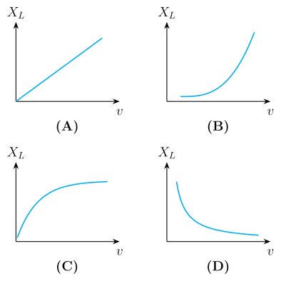
- KCET 2018Set A-11 markMCQQ.Which of the following, represents the variation of inductive reactance (XL) with the frequency of voltage source (v) ?
 (A)
(B)
(C)
(D)
(A)
(B)
(C)
(D)›Reveal solutionSolution
XL=2πνL is a linear law through the origin, so the XL–ν graph is a straight line from the origin.
Step 1 — Where inductive reactance comes from.
For a pure inductor driven by i=i0sinωt, the back-emf is Ldi/dt=ωLi0cosωt. Comparing the amplitude of the voltage with that of the current, the effective 'resistance' offered by the inductor is
XL=ωL=2πνL.
Physically: a faster-changing current induces a larger opposing emf, so the inductor obstructs high frequencies more.
Step 2 — Identify the functional form.
With L a constant of the coil,
XL=(2πL)ν,
which is of the form y=mx with m=2πL and zero intercept. So XL∝ν: a straight line passing through the origin.
Step 3 — Check the limits. …
🎓Unlock everything free for 14 days
- ✓Full step-by-step solutions
- ✓Concept-first explanations
- ✓Methods, shortcuts & mistakes
- ✓PYQ mapping + timed mock tests
Full access for 14 days. No credit card required.