Q.Draw a graph showing the intensity distribution of fringes due to diffraction at single slit.
🔒You're viewing a preview — the full solution, concept, methods & PYQ mapping are locked.
🔒 Start your 14-day free trial to unlock the full solution →Concept understanding — Single Slit Diffraction
Single Slit Diffraction: From Intuition to Precision
Imagine you're standing at the edge of a swimming pool and you send a straight wave toward a narrow gap in a wall. If the gap is wide, the wave mostly goes straight through — a clean "shadow" behind the wall. But if the gap is tiny, something strange happens: the wave spreads out in all directions beyond the gap, like ripples from a pebble. That spreading is diffraction.
Light does the same thing. When a parallel beam of light passes through a single narrow slit, it doesn't just make a sharp rectangle on a screen. Instead, you get a pattern: a bright central band, then dark bands (minima), then weaker bright bands (maxima), alternating as you move outward. The narrower the slit, the more the light spreads.
Why does this happen? The core idea
Light from every point across the slit travels to the screen. At any point on the screen, the light arriving from different parts of the slit has travelled different distances. If those path differences are exactly half a wavelength (λ/2), the waves cancel — you get darkness. If they are a whole wavelength (λ), they reinforce — you get a weaker bright band.
The key is that the slit is not a point source. It's a continuous line of sources, each sending out Huygens wavelets. The pattern is the result of interference among all those wavelets.
Common mistake
Students often think diffraction is just "bending around corners." That's part of it, but the real physics is interference between wavelets from different parts of the same slit. Without that interference, there would be no alternating dark and bright bands — just a fuzzy blur.
The precise condition for minima
Let the slit width be a and the wavelength be λ. For a point on a screen far away (the Fraunhofer or far-field condition), light rays from the slit are nearly parallel. The path difference between a wavelet from the top edge and one from the centre is 2asinθ, where θ is the angle from the straight-through direction.
For the first minimum, the wavelets from the top half of the slit cancel those from the bottom half exactly. That happens when the path difference between the two edges is exactly one wavelength:
asinθ=λ
For the second minimum, the slit can be divided into four equal zones, each cancelling the next, giving:
asinθ=2λ
In general, the condition for dark fringes (minima) is:
asinθ=mλfor m=±1,±2,±3,…
Notice m=0 is not a minimum — it's the centre of the bright central maximum.
What about the maxima?
The maxima occur roughly halfway between minima, but their positions are not given by a simple formula like asinθ=(m+21)λ. That formula works for double-slit interference, but for a single slit the maxima are slightly shifted. The exact positions come from solving a calculus problem (the derivative of the intensity function), but for exams you only need the minima condition and the fact that the central maximum is twice as wide as the others.
Quick exam fact
The angular width of the central maximum is 2θ1, where θ1 satisfies asinθ1=λ. So the central maximum spans from −λ/a to +λ/a in sinθ.
The intensity pattern (qualitative) …
In single-slit diffraction the wavelets from the slit interfere to give a broad, intense central maximum flanked by much weaker secondary maxima whose intensity falls off rapidly. …
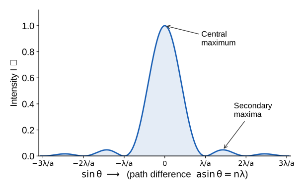
A central bright peak (twice as wide as the secondary bands) with rapidly diminishing side maxima; zeros at asinθ=mλ.
Concept. A single slit of width a acts as a set of Huygens wavelets. Path differences across the slit produce a diffraction pattern.
Why this shape. The intensity is I=I0(βsinβ)2 with β=λπasinθ. Minima occur where asinθ=mλ (m=±1,±2,…); secondary maxima lie roughly midway between minima with intensities ≈4.5%,1.6%… of the central peak.
…
- KCET 2022Set B-31 markMCQQ.In case of Fraunhoffer diffraction at a single slit the diffraction pattern on the screen is correct for which of the following statements? (A) Central dark band having uniform brightness on either side. (B) Central bright band having dark bands on either side. (C) Central dark band having alternate dark and bright bands of decreasing intensity on either side. (D) Central bright band having alternate dark and bright bands of decreasing intensity on either side.
›Reveal solutionSolution
In Fraunhofer single-slit diffraction, the central region is a bright band (the principal maximum), flanked by alternating dark and bright bands whose intensity falls off rapidly — so the correct description is option (D).
The key to this question is understanding what happens to light when it passes through a narrow slit and is observed on a distant screen — that’s Fraunhofer diffraction. Unlike geometrical optics, where a slit would just cast a sharp image of itself, diffraction spreads the light into a pattern of alternating bright and dark regions because different parts of the wavefront interfere with each other.
The central region is always the brightest and widest. Why? Because all the secondary wavelets from across the slit arrive in phase at the centre of the screen — they travel equal distances, so they add constructively. That gives a central bright band, not a dark one. This immediately eliminates options (A) and (C), which claim a central dark band.
Now, as you move away from the centre, the path difference between wavelets from opposite edges of the slit becomes significant. When that path difference equals exactly one wavelength, the wavelets cancel in pairs, producing the first dark band. Beyond that, a partial cancellation gives a weaker bright band, then another dark band, and so on. The intensity of these successive bright bands drops sharply — the first side maximum is only about 5% as bright as the central maximum, and the next is even fainter.
So the pattern is: central bright, then alternating dark and bright bands, with decreasing intensity. That matches option (D) exactly.
Watch outA common mistake is to confuse single-slit diffraction with double-slit interference. In double-slit, the central bright is flanked by equally bright maxima. In single-slit, the side maxima are much weaker — the intensity falls off as 1/x2 away from centre.
Let’s walk through the reasoning step by step.
- Set up the physics. In Fraunhofer diffraction, the slit width a is comparable to the wavelength λ, and the screen is far away. The condition for a dark band (destructive interference) is:
asinθ=mλ,m=±1,±2,…
Here θ is the angle from the centre. There is no m=0 dark band — m=0 gives θ=0, which is the centre, and that’s where all wavelets are in phase.
- Identify the central feature. At θ=0, the path difference between any two wavelets is zero, so they all interfere constructively. This produces the central maximum — a bright band. Its intensity is the highest in the pattern. …
- KCET 2022Set B-31 markMCQQ.When a Compact Disc (CD) is illuminated by small source of white light coloured bands observed. This due to (A) Interference (B) Reflection (C) Scattering (D) Diffraction
›Reveal solutionSolution
A CD's micron-spaced spiral track acts as a reflection grating, and dsinθ=nλ disperses white light into colours — the effect is diffraction.
1. The physical structure of a CD
The information on a CD is stored as a spiral of microscopic pits on a reflecting aluminium layer. Adjacent turns of the spiral are separated by about
d≈1.6 μm=1.6×10⁻⁶ m
Visible light has λ≈0.4–0.7 μm. Because d is of the same order as λ (only a few times larger), the surface is exactly the regime in which wave effects dominate — the rows of pits form a reflection diffraction grating.
2. Why that produces colours
For a grating, constructive interference of the light reflected from successive rows occurs when
dsinθ=nλ,n=1,2,3,…
Rearranged:
sinθ=dnλ
The angle θ therefore depends on λ. White light contains all visible wavelengths, so each colour is thrown off in a slightly different direction — red (large λ) at the largest angle, violet at the smallest. The eye, looking at one point on the disc, receives only one wavelength strongly, and the disc appears to be painted in shifting rainbow bands as you tilt it. This is dispersion by diffraction, exactly as with a grating or the colours on a butterfly wing.
3. Reject the alternatives …
🎓Unlock everything free for 14 days
- ✓Full step-by-step solutions
- ✓Concept-first explanations
- ✓Methods, shortcuts & mistakes
- ✓PYQ mapping + timed mock tests
Full access for 14 days. No credit card required.