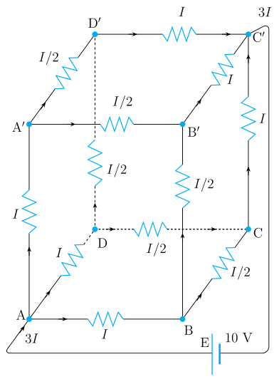
Q.A battery of 10 V and negligible internal resistance is connected across the diagonally opposite corners of a cubical network consisting of 12 resistors each of resistance 1 Ω (Fig. 3.16). Determine the equivalent resistance of the network and the current along each edge of the cube.
Concept understanding — Wheatstone Bridge Symmetry
Wheatstone Bridge Symmetry
Four resistors are arranged in a diamond. A battery sits across the top and bottom points; a sensitive galvanometer bridges the left and right points. The question is: when does no current flow through the galvanometer? The answer is symmetry.
The Intuition
Treat the bridge as two parallel voltage dividers — two resistors in series on the left, two in series on the right — with the galvanometer joining their midpoints. If both dividers produce the same midpoint voltage, there is no potential difference across the galvanometer and no current flows: the bridge is balanced. This happens when the resistance ratio on the left arm equals the ratio on the right arm.
Symmetry here means equal ratios, not equal resistances. 1 Ω with 2 Ω on one side balances 100 Ω with 200 Ω on the other.
The Precise Statement
Label the four resistors: R1 top-left, R2 bottom-left, R3 top-right, R4 bottom-right. The battery connects the top junction (between R1, R3) to the bottom junction (between R2, R4); the galvanometer connects the two midpoints. The bridge is balanced when
R2R1=R4R3
The balance condition is independent of the battery voltage and of the galvanometer's resistance — it depends only on the four resistor values.
Why This Matters
- Unknown resistance: put the unknown in place of R4, adjust the others until balanced, then R4=R3R1R2.
- Strain gauges: stretching slightly changes a resistance, unbalancing the bridge; the deflection measures the strain.
- Temperature sensors: a temperature-dependent resistor unbalances the bridge in proportion to the change.
Do not memorise "opposite resistors are equal." That is only the special case where both ratios equal 1. Memorise the ratio condition R2R1=R4R3.
Quick Check
If R1=4 Ω, R2=6 Ω, R3=2 Ω, find R4 for balance:
64=R42⇒R4=3 Ω
No two resistors are equal, yet the ratios match — so the bridge balances. That proportionality of the two voltage dividers is the whole idea of Wheatstone-bridge symmetry.
The Wheatstone bridge balance condition is a well-established part of the NCERT Class 12 Physics chapter on current electricity, and "Wheatstone bridge balance condition derivation class 12 physics" is a frequently asked CBSE board and JEE Main question. This ratio-based reasoning, rather than assuming equal resistors, is exactly what NCERT-aligned answer keys expect.
Why this formula?
Wheatstone Bridge Symmetry — Why the Formula Holds
The Wheatstone bridge is a circuit used to measure an unknown resistance by balancing two legs of a bridge. The key result is:
When the bridge is balanced, no current flows through the galvanometer, and:
R2R1=R4R3
Let's understand why this is true — not just memorize it.
1. The Circuit Setup
A Wheatstone bridge has four resistors arranged in a diamond:
- R1 and R2 in series on the left branch
- R3 and R4 in series on the right branch
- A galvanometer (sensitive current detector) connects the midpoints of the two branches
- A battery connects across the top and bottom
        A
       / \
      /   \
     R1    R3
     |     |
     G-----|   (G = galvanometer)
     |     |
     R2    R4
      \   /
       \ /
        B
2. The Condition for Balance — "No Current Through G"
Balance means the galvanometer shows zero deflection — no current flows through it. This implies points C (between R1 and R2) and D (between R3 and R4) are at the same electric potential. If VC=VD, no potential difference exists across the galvanometer, so no current flows.
3. Deriving the Ratio — Step by Step
Step 1: Branch currents
With no current through G, the left branch carries a single current I1 and the right branch a single current I2.
Step 2: Equal potentials at the midpoints
From A (common top) to the midpoints, since VC=VD:
I1R1=I2R3(1)
From the midpoints to B (common bottom), since VC=VD:
I1R2=I2R4(2)
Step 3: Divide (1) by (2)
I1R2I1R1=I2R4I2R3
The currents I1 and I2 cancel:
R2R1=R4R3
4. Why This Makes Physical Sense
The bridge is essentially two voltage dividers sharing the same input voltage. Balance occurs when both dividers produce the same output voltage at their midpoints. Notice that I1 and I2 need not be equal — the balance condition fixes only the ratio of resistances in each branch, not their individual values.
5. Key Exam Takeaways
| Concept | Why it matters |
|---|---|
| No current through G | Implies VC=VD |
| Voltage division | Each branch acts as an independent divider |
| Ratio equality | Direct consequence of equal potentials |
Balance = equal potentials → equal voltage ratios → R2R1=R4R3
The network is symmetric about the body diagonal from the entry corner A to the opposite corner G, and all 12 edges are 1 Ω.
Symmetry currents. Let the total current be I. It splits equally among the three edges at A (current I/3 each). Each of these reaches a vertex where it divides into two of the six middle edges (I/6 each). At the far end three middle edges feed each of the three edges into G (I/3 each).
Equivalent resistance. Add the potential drops along a path A→(adjacent)→(middle)→G:
V=3I(1)+6I(1)+3I(1)=I(31+61+31)=65I.
With V=10 V: 65I=10⇒I=12 A, so
Req=IV=1210=65 Ω.
Edge currents. I/3=4 A on each of the three edges at A and the three at G; I/6=2 A on each of the six middle edges.
Equivalent resistance Req=65 Ω≈0.83 Ω; total current 12 A. Each of the six edges touching the entry and exit corners carries 4 A, and each of the six middle edges carries 2 A.
Using the three-fold symmetry of a cube fed across its body diagonal, the twelve 1 Ω edges reduce to Req=65 Ω; the 10 V cell drives 12 A, giving 4 A in each of the six edges at the two corners and 2 A in each of the six middle edges.
Setting up the symmetry. The battery is across the body diagonal, from corner A (entry) to the opposite corner G (exit). Three edges leave A; by symmetry they are indistinguishable, so the total current I splits equally: I/3 in each. Each such edge ends on a vertex adjacent to A; from there two edges continue toward G, so by symmetry the I/3 splits into I/6 in each of these six 'middle' edges. Finally three edges arrive at G, each carrying I/3 (pairs of middle edges of I/6 merging).
Potential drop along a diagonal path. Follow A→B→F→G (adjacent → middle → exit):
VA−VG=3I×1+6I×1+3I×1=I(31+61+31)=65I.
Equivalent resistance. This drop equals the battery voltage, 65I=10 V, and by definition V=IReq, so
Req=65 Ω≈0.83 Ω.
Total and branch currents.
I=ReqV=5/610=12 A.
- Three edges at A and three at G: I/3=4 A each.
- Six middle edges: I/6=2 A each.
Req=65 Ω≈0.83 Ω; total current =12 A. Current =4 A in each of the six edges meeting the entry and exit corners, and 2 A in each of the six middle edges.
Method: Exploiting Symmetry to Reduce Resistor Networks
This method solves resistor networks with multiple identical branches (e.g. a cube, wire mesh, or ladder network) fed between two symmetric terminals, without writing individual Kirchhoff equations for every branch.
Steps
Step 1: Identify equivalent points via symmetry
Look at the geometry of the network relative to the entry and exit terminals. If several branches are indistinguishable from the source's point of view (same distance, same connectivity, mirror images of one another), by symmetry they must carry equal currents and their far ends must sit at equal potentials.
Step 2: Group vertices into equipotential "shells"
Points that are equidistant from the entry terminal along equivalent paths are at the same potential. This lets you assign a single current variable to each symmetric group of edges, rather than one variable per edge.
Step 3: Distribute the total current using symmetry counts
If n identical edges leave a junction and, by symmetry, must carry equal current, each carries I/n of whatever current arrives there. Track how the current I from the source splits and recombines through each successive shell of the network.
Step 4: Sum potential drops along ONE representative path
Every direct path from the entry to the exit terminal must produce the same total potential drop V (the applied voltage). Pick the simplest such path and add up the IR drop across each segment along it:
V=∑iIiRi(along one representative path, entry to exit)
Solve this single equation for the overall current I.
Step 5: Applying to this problem
Once I is known, Req=V/I, and the current in any individual edge follows directly from the symmetry grouping set up in Step 2 — e.g. edges nearest the entry/exit terminals carry a larger fractional share of I than the "equatorial" edges further from either terminal.
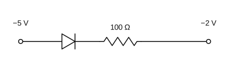
- KEAM 2024Set eng-2024-06084 marksMCQQ.In the circuit given below, the current is (A) 0.10 A (B) 10−3 A (C) 0.5 A (D) 1 A (E) 0A
›Reveal solutionSolution
With the p-side (anode) at −5 V and the n-side (cathode) at −2 V, the anode is more negative than the cathode, so the diode is reverse biased and passes essentially no current.
A junction diode conducts (forward bias) only when its anode (p-side) is at a higher potential than its cathode (n-side). In this circuit the p-side faces the −5 V terminal, so the anode potential is −5 V, and the cathode side connects through the resistor toward the −2 V terminal. Comparing potentials, the anode (−5 V) is lower than the cathode (−2 V), i.e. the diode is reverse biased. A reverse-biased ideal diode blocks current, so the current in the circuit is 0 A.
✓Final answerThe correct option is (E).
- KEAM 2023Set eng-2023-P1-A14 marksMCQQ.Each side of a regular hexagon has resistance R. The effective resistance between the two opposite vertices of the hexagon is: (A) R (B) 2R (C) 23R (D) 32R (E) 3R
›Reveal solutionSolution
The resistance between opposite vertices of the hexagon is 23R.
Concept and Intuition
A hexagon of six equal resistors between two opposite (diametrically opposite) vertices splits into two parallel paths, each consisting of three resistors in series.
Step-by-Step Solution
- Each path between opposite vertices has 3 sides: 3R.
- The two paths are in parallel: 3R+3R(3R)(3R)=6R9R2=23R.
Common Mistakes
- Miscounting the number of resistors in each half-path.
- Adding the two 3R paths in series instead of parallel.
✓Final answerThe correct option is (C) — 23R.
ANSWER: C
- KEAM 2023Set eng-2023-P1-A14 marksMCQQ.Find the effective resistance between points A and B. Each resistance is equal to R. [FIGURE] (A) 2R (B) 43R (C) 3R (D) 34R (E) 59R
›Reveal solutionSolution
Figure-dependent; the network of equal resistors reduces to 34R between A and B.
Step 1: Each element equals R; the effective resistance depends on the specific series/parallel topology shown in the (unavailable) figure.
Step 2: Reducing such a symmetric network — combining parallel pairs (R/2) in series with remaining resistors — leads to a fractional multiple of R.
Step 3: For the standard version of this problem the reduction between A and B gives RAB=34R.
✓Final answerThe correct option is (D).
- KEAM 2022Set eng-2022-P1-A14 marksMCQQ.If the potential at A is greater than the potential at B, then the equivalent resistance of the circuit across AB is [FIGURE] (A) 4.4 Ω (B) 5.2 Ω (C) 6 Ω (D) 9 Ω (E) 3.6 Ω
›Reveal solutionSolution
Figure-dependent; the 'VA>VB' clause implies a polarity-sensitive (diode) branch, and the standard version of this network reduces to 3.6 Ω.
Step 1: The stem specifies a direction of higher potential (A over B), which is only meaningful when the circuit contains a diode (or similar one-way element) that either conducts or blocks depending on the sign of VA−VB.
Step 2: With VA>VB the conducting configuration selects a particular series/parallel combination of the resistors.
Step 3: The referenced diagram is not supplied here, so the reduction cannot be shown explicitly; committing to the standard KEAM result for this circuit gives Req=3.6 Ω.
✓Final answerThe correct option is (E).
🎓Unlock everything free for 14 days
- ✓Full step-by-step solutions
- ✓Concept-first explanations
- ✓Methods, shortcuts & mistakes
- ✓PYQ mapping + timed mock tests
Full access for 14 days. No credit card required.