Four resistors are arranged in a diamond. A battery sits across the top and bottom points; a sensitive galvanometer bridges the left and right points. The question is: when does no current flow through the galvanometer? The answer is symmetry.
The Intuition
Treat the bridge as two parallel voltage dividers — two resistors in series on the left, two in series on the right — with the galvanometer joining their midpoints. If both dividers produce the same midpoint voltage, there is no potential difference across the galvanometer and no current flows: the bridge is balanced. This happens when the resistance ratio on the left arm equals the ratio on the right arm.
Note
Symmetry here means equal ratios, not equal resistances. 1Ω with 2Ω on one side balances 100Ω with 200Ω on the other.
The Precise Statement
Label the four resistors: R1 top-left, R2 bottom-left, R3 top-right, R4 bottom-right. The battery connects the top junction (between R1, R3) to the bottom junction (between R2, R4); the galvanometer connects the two midpoints. The bridge is balanced when
R2R1=R4R3
Important
The balance condition is independent of the battery voltage and of the galvanometer's resistance — it depends only on the four resistor values.
Why This Matters
Unknown resistance: put the unknown in place of R4, adjust the others until balanced, then R4=R3R1R2.
Strain gauges: stretching slightly changes a resistance, unbalancing the bridge; the deflection measures the strain.
Temperature sensors: a temperature-dependent resistor unbalances the bridge in proportion to the change. …
Why this formula?
Wheatstone Bridge Symmetry — Why the Formula Holds
The Wheatstone bridge is a circuit used to measure an unknown resistance by balancing two legs of a bridge. The key result is:
When the bridge is balanced, no current flows through the galvanometer, and:
R2R1=R4R3
Let's understand why this is true — not just memorize it.
1. The Circuit Setup
A Wheatstone bridge has four resistors arranged in a diamond:
R1 and R2 in series on the left branch
R3 and R4 in series on the right branch
A galvanometer (sensitive current detector) connects the midpoints of the two branches
2. The Condition for Balance — "No Current Through G"
Balance means the galvanometer shows zero deflection — no current flows through it. This implies points C (between R1 and R2) and D (between R3 and R4) are at the same electric potential. If VC=VD, no potential difference exists across the galvanometer, so no current flows.
3. Deriving the Ratio — Step by Step
Step 1: Branch currents
With no current through G, the left branch carries a single current I1 and the right branch a single current I2.
Step 2: Equal potentials at the midpoints
From A (common top) to the midpoints, since VC=VD:
I1R1=I2R3(1)
From the midpoints to B (common bottom), since VC=VD:
Concept: Kirchhoff's laws applied to an unbalanced bridge network
Figure 3.17
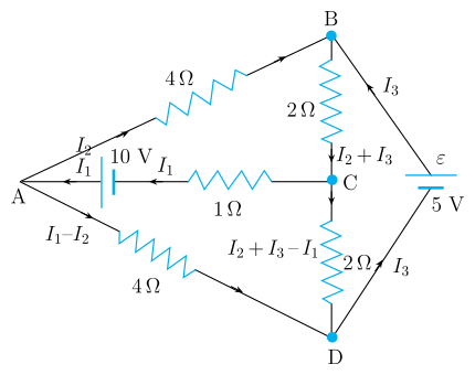
A 5V cell sits in the diagonal BD, so this bridge is not balanced — the shortcut R1/R2=R3/R4 does not apply, and the network must be solved directly with Kirchhoff's rules. …
A 5V cell sits directly in diagonal BD, so this bridge is unbalanced and must be solved with Kirchhoff's rules, not the balance shortcut. Solving via node potentials (VD=0 reference) gives VA=7.5V, VB=5V, VC=0V, and hence IAC=2.5A, IAB=0.625A, IAD=1.875A, IBC=2.5A, ICD=0A, IBD=1.875A.
Figure 3.17
The network
The four nodes A,B,C,D form a bridge: arms AB=AD=4Ω, arms BC=CD=2Ω, diagonal AC carries a 1Ω resistor in series with a 10V cell, and diagonal BD carries an (ideal, resistance-free) 5V cell. Because an emf sits directly in a diagonal, the balanced-bridge condition R1/R2=R3/R4 (which only applies when the diagonal carries no source and the bridge is at null deflection) is irrelevant here — this must be solved as a general Kirchhoff's-laws problem.
Solving by node potentials
Take D as the reference node, VD=0. The diagonal BD is an ideal 5V cell directly connecting B and D, so it fixes B's potential immediately:
VB=VD+5=5V.
For the branch AC (a 1Ω resistor in series with a 10V cell), the current flowing from C to A, IAC, obeys
IAC=1VC−VA+10.
Kirchhoff's junction rule at A: current entering from C equals current leaving through AB and AD:
(VC−VA+10)=4VA−VB+4VA−VD.
Substituting VB=5,VD=0 and simplifying:
4VC−4VA+40=2VA−5⇒VA=64VC+45.(i)
Kirchhoff's junction rule at C: current entering from B equals current leaving through AC and CD:
2VB−VC=(VC−VA+10)+2VC−VD.
Substituting and simplifying:
5−VC=3VC−2VA+20⇒VA=2VC+7.5.(ii)
Setting (i) = (ii): 64VC+45=2VC+7.5⇒4VC+45=12VC+45⇒VC=0, and then VA=7.5V.
Method: Solving an Unbalanced Bridge by Node (Nodal) Potentials
Use this whenever a resistor network — a bridge or any multi-loop circuit — contains a source (battery/cell) placed directly in an interior branch, so the simple balance-ratio shortcut (R1/R2=R3/R4) does not apply and the full network must be solved.
Steps
Step 1: Check whether the balance condition applies
Compute the two arm ratios of the bridge (e.g. AB/BC vs AD/DC). If they're unequal, OR if a real EMF source (not just a galvanometer) sits in the bridging diagonal, the network is unbalanced — you cannot assume zero current in that branch and must solve the full circuit.
Step 2: Choose a reference node and assign potentials
Pick one node as the reference (set its potential to 0). If an ideal EMF source with no internal resistance directly connects two nodes, it immediately fixes their potential difference — use this to eliminate one unknown right away:
VX−VY=ε(across an ideal-source branch)
Step 3: Apply Kirchhoff's junction rule at every unfixed node …
Same / Similar Concept — real previous-year questions on the same or a closely similar concept, not this exact question.
KEAM 2024Set eng-2024-06084 marksMCQ
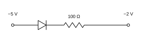
Q.In the circuit given below, the current is
(A) 0.10 A
(B) 10−3 A
(C) 0.5 A
(D) 1 A
(E) 0A
›Reveal solutionSolution
With the p-side (anode) at −5 V and the n-side (cathode) at −2 V, the anode is more negative than the cathode, so the diode is reverse biased and passes essentially no current.
A junction diode conducts (forward bias) only when its anode (p-side) is at a higher potential than its cathode (n-side). In this circuit the p-side faces the −5 V terminal, so the anode potential is −5 V, and the cathode side connects through the resistor toward the −2 V terminal. Comparing potentials, t …
Q.Each side of a regular hexagon has resistance R. The effective resistance between the two opposite vertices of the hexagon is:
(A) R
(B) 2R
(C) 23R
(D) 32R
(E) 3R
›Reveal solutionSolution
The resistance between opposite vertices of the hexagon is 23R.
Concept and Intuition
A hexagon of six equal resistors between two opposite (diametrically opposite) vertices splits into two parallel paths, each consisting of three resistors in series.
Step-by-Step Solution
Each path between opposite vertices has 3 sides: 3R.
The two paths are in parallel: 3R+3R(3R)(3R)=6R9R2=23R. …
Q.If the potential at A is greater than the potential at B, then the equivalent resistance of the circuit across AB is [FIGURE]
(A) 4.4Ω
(B) 5.2Ω
(C) 6Ω
(D) 9Ω
(E) 3.6Ω
›Reveal solutionSolution
Figure-dependent; the 'VA>VB' clause implies a polarity-sensitive (diode) branch, and the standard version of this network reduces to 3.6Ω.
Step 1: The stem specifies a direction of higher potential (A over B), which is only meaningful when the circuit contains a diode (or similar one-way element) that either conducts or blocks depending on the sign of VA−VB.
Step 2: With VA>VB the conducting configuration selects a particular series/parallel combination of the resistors. …