Physics · Ch 4 — Thermodynamics
Sterling Cycle
Sterling Cycle
The Sterling cycle (more commonly spelled Stirling cycle) is a further example of a closed thermodynamic cycle, distinct from both the ordinary heat-engine cycle of Section 4.8.2 and the Carnot cycle of Section 4.11 — the Sterling engine is built around it. The working substance used in a practical Sterling engine is typically a gas such as air, helium, hydrogen, or nitrogen (rather than, e.g., a fuel-air combustion mixture). Every one of the four processes making up the ideal Sterling cycle is reversible. When heat is supplied to the gas, the Sterling engine produces useful mechanical work, exactly like an ordinary heat engine; but when mechanical work is instead done ON the gas, the SAME cycle run in reverse works as a refrigerator. This reversed Sterling cycle, in fact, is used extensively and specifically in the field of cryogenics — the study and production of extremely low temperatures — both to reach extremely low temperatures directly and to liquefy gases such as the ones listed above.
The ideal Sterling cycle consists of four steps, forming a closed loop between two fixed temperatures (hot) and (cold), with heat absorbed at and heat rejected at — structurally, TWO isothermal legs (like the Carnot cycle) but connected by one isochoric leg and one isobaric leg (rather than the Carnot cycle's two adiabatic legs):
-
Isothermal expansion (A to B): the gas is heated at the constant, fixed temperature , absorbing heat ; useful work is done by the gas during this leg, exactly as in an ordinary isothermal expansion (Section 4.7.3.2).
-
Isochoric process (B to C): part of the heat that was absorbed in the previous (A-to-B) step is now released by the gas — at constant volume, so no work is done during this leg (Section 4.7.3.4) — and this released heat is carried over internally to be reused in the final (D-to-A) leg of the cycle. The gas's temperature falls from down to during this step.
-
Isothermal compression (C to D): the gas is compressed at the constant, fixed temperature , and the heat generated during this compression is rejected to the sink (the coolant); the gas's temperature is held at throughout this leg. …
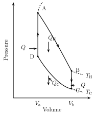
Drawn by us to help you understand the concept clearly, and verified to make sure it's accurate. For exams, practice from your textbook's own diagram.
What this p-V diagram shows. The graph plots pressure p (vertical axis) against volume V (horizontal axis); the area under the curve equals the work done during the process, and the shape of the path tells you how pressure and volume change tog …
Internet my friend — links the textbook itself suggests for further study:
- https://opentextbc.ca/physicstestbook2/chapter/the-first-law-of-thermodynamics/
- https://opentextbc.ca/physicstestbook2/chapter/introduction-to-the-second-law-of-thermodynamics-heat-engines-and-their-efficiency/
- https://opentextbc.ca/physicstestbook2/chapter/the-first-law-of-thermodynamics-and-some-simple-processes/
- https://courses.lumenlearning.com/boundless-physics/chapter/introduction-8/
- http://heatengine-sundervallii.blogspot.com/2010/10/everyday-examples-of-heat-engine.html …