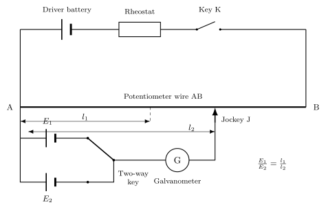
Comparison of EMF — The Intuition
Imagine you have two batteries, but you don't know their voltages. You want to find out which is stronger, and by how much. The obvious way is to connect a voltmeter across each one. But a voltmeter draws a small current, and that tiny current causes a voltage drop inside the battery itself (due to its internal resistance). So the reading you get is not the true EMF — it's the terminal voltage, which is slightly less.
If you want the true EMF — the voltage the battery would produce if no current flowed through it — you need a method that doesn't draw any current at all. That's exactly what a potentiometer does.
The Core Idea
A potentiometer is a long uniform wire with a known potential difference across its ends. By sliding a contact along the wire, you can "tap off" any fraction of that total potential difference. When you connect a cell to this tapped voltage, you adjust the sliding contact until the galvanometer shows zero deflection — meaning no current flows through the cell. At that exact point, the potential difference across the tapped length of wire exactly balances the cell's EMF.
Because no current flows through the cell at balance, the internal resistance of the cell has no effect. You are measuring the true EMF.
Comparing Two Cells
Now suppose you have two cells, with EMFs ε1 and ε2. You do the balancing experiment for each one, using the same potentiometer wire with the same total voltage across it.
For the first cell, the balancing length is l1. That means the potential drop per unit length of the wire (call it k) times l1 equals ε1:
ε1=kl1
For the second cell, the balancing length is l2:
ε2=kl2
Since k is the same in both cases (same wire, same total voltage), you can divide the two equations:
ε2ε1=l2l1
ε2ε1=l2l1
That's the entire principle. You don't need to know k, you don't need to know the total voltage across the wire — you only need the two balancing lengths.
Why This Works — The Precision
The key condition is that the potentiometer wire must have a uniform cross-section and uniform resistivity, so that the potential drop per unit length is constant. If the wire is not uniform, the ratio of lengths won't equal the ratio of EMFs.
Also, the total voltage across the wire must remain constant during both measurements. If the driving cell (the one supplying the potentiometer) fluctuates, k changes and the comparison becomes unreliable. …