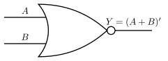
The NOR Gate: "Not OR"
Imagine you're at home with a friend. Your parent says: "I'll turn off the Wi-Fi if neither of you has finished homework." That's a NOR gate in real life. The Wi-Fi stays on (output = 1) only when both of you have finished homework (both inputs = 0). If even one person hasn't finished, the Wi-Fi goes off.
That's the core idea: NOR gives a 1 only when every single input is 0. The moment any input becomes 1, the output drops to 0.
From OR to NOR
You already know the OR gate: output is 1 if at least one input is 1. The NOR gate is simply an OR gate followed by a NOT gate (inverter). The name itself tells you: Not OR.
Y=A+B
For two inputs A and B, the truth table is:
| A | B | A + B (OR) | A+B (NOR) |
|---|
| 0 | 0 | 0 | 1 |
| 0 | 1 | 1 | 0 |
| 1 | 0 | 1 | 0 |
| 1 | 1 | 1 | 0 |
Notice the pattern: the NOR column is the exact opposite of the OR column. Where OR gives 1, NOR gives 0 — and vice versa.
The precise statement
A NOR gate outputs 1 only when all its inputs are 0. For any other combination of inputs, the output is 0.
For n inputs, the output is 1 if and only if every input is 0. That's the complete, exam-ready definition.
Why "universal gate"?
NOR is one of two universal gates (the other is NAND). This means you can build any logic gate — AND, OR, NOT, XOR — using only NOR gates. For example:
- NOT from NOR: connect both inputs together. Y=A+A=A
- OR from NOR: NOR followed by a NOT (which is another NOR with tied inputs). Y=A+B=A+B
- AND from NOR: use De Morgan's law: A+B=A⋅B, so A⋅B=A+B
In exam problems, if you're asked to implement a circuit using only NOR gates, remember: NOR is OR followed by NOT. To get OR back, just add another NOR as a NOT at the end.
Common mistake to avoid …