Physics · Ch 6 — Electromagnetic Induction
Mutual Inductance
Mutual Inductance
Mutual Inductance
Mutual inductance is the ability of one coil to induce an electromotive force (emf) in a nearby coil due to a change in its own current. It quantifies the magnetic coupling between two circuits.
Physical Setup: Two Co-axial Solenoids
Consider two long, co-axial solenoids of the same length :
- Inner solenoid : radius , turns per unit length , total turns .
- Outer solenoid : radius , turns per unit length , total turns .
The solenoids are long enough that , so edge effects are negligible and the magnetic field inside each is uniform.
Case 1: Current in Outer Solenoid
When a current flows through , it produces a uniform magnetic field inside it:
This field passes through the inner solenoid . The magnetic flux through one turn of is .
The total flux linkage with (which has turns) is:
By definition, the mutual inductance (of with respect to ) satisfies:
Comparing, we get:
Case 2: Current in Inner Solenoid
Now, let a current flow through . Its magnetic field is confined inside (since the solenoids are long):
This field passes through the outer solenoid only over the area (the cross-section of ). The flux through one turn of is .
The total flux linkage with (which has turns) is:
By definition, the mutual inductance (of with respect to ) satisfies:
Comparing, we get:
Reciprocity Theorem
From the two calculations, we see:
This equality is general — it holds for any pair of coils, not just co-axial solenoids. It is very useful when one configuration is easier to calculate than the other.
Effect of a Magnetic Medium
If the solenoids are filled with a medium of relative permeability , the mutual inductance becomes:
Dependence on Geometry and Orientation
Mutual inductance depends on:
- The separation between the coils.
- Their relative orientation (angle between their axes).
Example: Two Concentric Circular Coils
Consider two concentric circular coils:
- Small coil (radius ) inside a large coil (radius ), with .
- Their centres coincide and they are co-axial.
Let current flow through the outer coil. The magnetic field at its centre is:
Since , this field is approximately uniform over the small coil's area. The flux through the small coil is: …
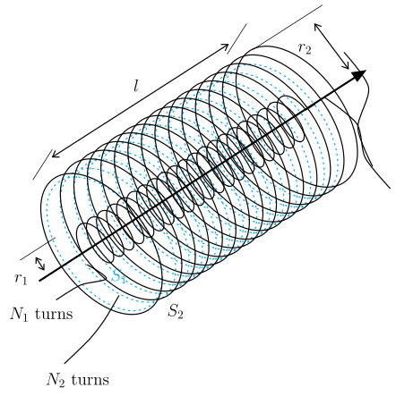
Drawn by us to help you understand the concept clearly, and verified to make sure it's accurate. For exams, practice from your NCERT textbook's own diagram.
What the figure shows
The diagram depicts two long solenoids sharing the same central axis (co‑axial) and the same length . The outer solenoid is drawn as a visible blue helical coil of radius . Inside it, the inner solenoid is shown with dashed or lighter windings, having a smaller radius . A double‑headed arrow above the cylinder marks the common length . A short radial arrow at the upper‑right indicates (outer radius), and another radial arrow at the lower‑left indicates (inner radius). The labels and identify the coils, and below them the text “ turns” points to the inner coil and “ turns” to the outer coil.
Physical idea taught
The figure illustrates the geometry for calculating mutual inductance between two co‑axial solenoids. The key idea is that a current in one solenoid produces a magnetic field that threads through the other solenoid, linking its turns. Because the solenoids are long (), the magnetic field inside each is nearly uniform and confined to its interior. This allows a simple calculation of the flux linkage and hence the mutual inductance.
Key formulas developed from this figure
The textbook derives the mutual inductance (also called the coefficient of mutual induction) for this arrangement. For a current in the outer solenoid , the magnetic field inside is , where is the number of turns per unit length of . The flux through each turn of the inner solenoid is , and the total flux linkage with (which has turns) is
Comparing with the definition gives
Similarly, for a current in the inner solenoid, the field is confined inside , so the flux linkage with (which has turns) is
and thus
Hence the mutual inductance is symmetric: …